Front matter
Get started with MicroPython on Raspberry Pi Pico, 2nd Edition
Copyright Page
Get started with MicroPython on Raspberry Pi Pico
by Gareth Halfacree and Ben Everard
ISBN: 978-1-912047-29-1
Copyright © 2024 Gareth Halfacree and Ben Everard
Printed in the United Kingdom
Published by Raspberry Pi Ltd., 194 Science Park, Cambridge, CB4 0AB
Editors: Brian Jepson, Liz Upton
Technical Editors: Brian Jepson, Jo Hinchliffe
Interior Designer: Sara Parodi
Production: Nellie McKesson
Photographer: Brian O’Halloran
Illustrator: Sam Alder
Graphics Editor: Natalie Turner
Publishing Director: Brian Jepson
Head of Design: Jack Willis
CEO: Eben Upton
January 2025: Second Edition, Second Printing
June 2024: Second Edition
January 2021: First Edition
The publisher, and contributors accept no responsibility in respect of any omissions or errors relating to goods, products or services referred to or advertised in this book. Except where otherwise noted, the content of this book is licensed under a Creative Commons Attribution-NonCommercial-ShareAlike 3.0 Unported (CC BY-NC-SA 3.0)
Welcome
You might think of computers as things you stick on your desk and type on. That is certainly one type of computer, but it’s not the only type. In this book, we’re looking at microcontrollers — small processing units with a bit of memory that are good at controlling other hardware. You probably have lots of microcontrollers in your house already.
There’s a good chance your washing machine is controlled by a microcontroller; maybe your watch is; you might find one in your coffee machine or microwave. All these microcontrollers already have software running on them and the manufacturers make it hard to make any kind of change to that software.
A Raspberry Pi Pico, on the other hand, is a microcontroller that you can easily program (and reprogram!) over a USB connection. In this book, we’ll look at how to get started with Pico and how to make it work with other electronic components. By the end of the book, you’ll know how to create your own programmable electronic contraptions. What you do with them is up to you.
You can find this book’s example code, errata, and other resources in its GitHub repository at rptl.io/pico-resources-2e. If you’ve found what you believe is a mistake or error in the book, please let us know by using our errata submission form at rptl.io/pico-errata-2e.
About the authors
Gareth Halfacree is a freelance technology journalist, writer, and former system administrator in the education sector. With a passion for open-source software and hardware, he was an early adopter of the Raspberry Pi platform and has written several publications on its capabilities and flexibility. He can be found on Mastodon as @ghalfacree@mastodon.social or via his website at freelance.halfacree.co.uk.
Ben Everard is a geek who has stumbled into a career that lets him play with new hardware. As the editor of HackSpace magazine (hsmag.cc), he spends more time than he really should experimenting with the latest (and not-so latest) DIY tech. He lives in Bristol with his wife and two daughters in a house that’s slowly filling up with electronics equipment and 3D printers.
Colophon
Raspberry Pi is an affordable way to do something useful, or to do something fun.
Democratising technology — providing access to tools — has been our motivation since the Raspberry Pi project began. By driving down the cost of general-purpose computing to below $5, we’ve opened up the ability for anybody to use computers in projects that used to require prohibitive amounts of capital. Today, with barriers to entry being removed, we see Raspberry Pi computers being used everywhere from interactive museum exhibits and schools to national postal sorting offices and government call centres. Kitchen table businesses all over the world have been able to scale and find success in a way that just wasn’t possible in a world where integrating technology meant spending large sums on laptops and PCs.
Raspberry Pi removes the high entry cost to computing for people across all demographics: while children can benefit from a computing education that previously wasn’t open to them, many adults have also historically been priced out of using computers for enterprise, entertainment, and creativity.
Raspberry Pi eliminates those barriers.
Raspberry Pi Press
Raspberry Pi Press is your essential bookshelf for computing, gaming, and hands-on making. We are the publishing imprint of Raspberry Pi Ltd. From building a PC to building a cabinet, discover your passion, learn new skills, and make awesome stuff with our extensive range of books and magazines.
The MagPi
The MagPi is the official Raspberry Pi magazine. Written for the Raspberry Pi community, it is packed with Pi-themed projects, computing and electronics tutorials, how-to guides, and the latest community news and events.
Get to know your Raspberry Pi Pico
Get acquainted with your powerful new microcontroller board and learn how to attach pin headers and install MicroPython to program it
Raspberry Pi Pico-family boards are miniature marvels, putting the same technology that underpins everything from smart home systems to industrial factories in the palm of your hand. Whether you’re looking to learn about the MicroPython programming language, take your first steps in physical computing, or want to build a hardware project, Pico — and the amazing community behind it — will support you every step of the way.
Raspberry Pi Pico devices are microcontroller development boards. They’re designed for experimenting with physical computing using a special type of processor: a microcontroller. The size of a stick of gum, the Pico boards pack a surprising amount of power thanks to the chip at their centre: an RP2040 microcontroller for Pico and Pico W, and an RP2350 for Pico 2 and Pico 2 W.
Raspberry Pi Pico boards aren’t designed to replace Raspberry Pi, which is an entirely different class of device known as a single-board computer. You might use Raspberry Pi to play games, write software, or browse the web. Raspberry Pi Pico is designed for physical computing projects, where it is used to control anything from LEDs and buttons to sensors, motors, and even other microcontrollers.
Throughout this book you’ll learn all about the Raspberry Pi Pico boards, but the skills you learn will also apply to any development board based around the RP2040 or RP2350 microcontrollers — and even other devices, so long as they are compatible with the MicroPython programming language.
A guided tour of Raspberry Pi Pico 2
A Raspberry Pi Pico-family microcontroller — ‘Pico’ for short — is a lot smaller than even Raspberry Pi Zero, the most compact of Raspberry Pi’s single-board computers. Despite this, it includes a lot of features — all accessible using the pins around the edge of the board. The second-generation Pico series is available in two versions, Pico 2 and Pico 2 W; you’ll see the difference between the two later. If you have an original Pico or Pico W, the layout of the board is generally the same.
Figure 1-1 shows Raspberry Pi Pico 2 as seen from above. If you look at the longer edges, you’ll see gold-coloured sections with small holes. These are the pins which provide the RP2040 microcontroller with connections to the outside world — known as input/output (IO).
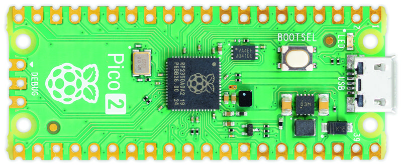
The pins on your Pico 2 are very similar to the pins that make up the general-purpose input/output (GPIO) header on a Raspberry Pi — but while most Raspberry Pi single-board computers come with the physical metal pins already attached, Pico boards do not.
If you want to buy a Pico 2 with headers mounted, look for Raspberry Pi Pico 2 or Pico 2 W with headers. There’s a good reason to offer models without headers attached: look at the outer edge of the circuit board and you’ll see it’s bumpy, with little circular cut-outs (Figure 1-2).
These bumps create what is called a castellated circuit board, which can be soldered on top of other circuit boards without using any physical metal pins. It’s very helpful in builds where you need to keep the height to a minimum, making for a smaller finished project. If you buy an off-the-shelf gadget powered by a Pico-family microcontroller, it’ll almost certainly be fitted using the castellations.
The holes just inwards from the bumps are to accommodate 2.54mm male pin headers. You’ll recognise them as the same type of pins used on the bigger Raspberry Pi’s GPIO header. By soldering these in place pointing downwards, you can push your Pico into a solderless breadboard to make it easy to connect and disconnect new hardware — great for experiments and rapid prototyping!
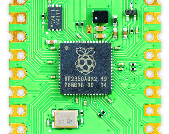
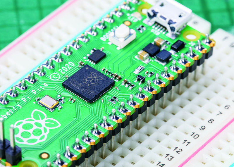
The chip at the centre of your Pico 2 (Figure 1-3) is an RP2350 microcontroller. This is a custom integrated circuit (IC), designed and built by Raspberry Pi to operate as the brains of your Pico and other microcontroller-based devices. If you look at it closely, you’ll see a Raspberry Pi logo etched into the top of the chip along with a series of letters and numbers which let engineers track when and where the chip was made.
At the top of your Pico is a micro USB port (Figure 1-4). This provides power to make your Pico run, and also sends and receives data that lets your Pico talk to a Raspberry Pi or another computer via its USB port. This is how you’ll load programs onto your Pico.
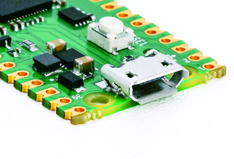
If you hold your Pico up and look at the micro USB port head-on, you’ll see it’s shaped so it’s narrower at the bottom and wider at the top. Take a micro USB cable, and you’ll see its connector is the same.
The micro USB cable will only go into the micro USB port on your Pico one way up. When you’re connecting it, make sure to line the narrow and wide sides up the right way around — you could damage your Pico if you try to brute-force the micro USB cable in the wrong way up!
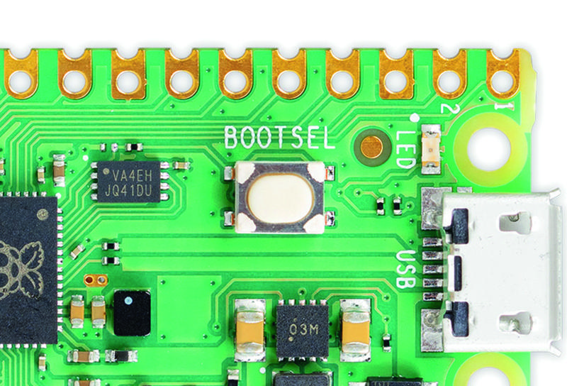
Just below the micro USB port is a small button marked ‘BOOTSEL’, shown in Figure 1-5. ‘BOOTSEL’ is short for boot selection, which switches your Pico between two start-up modes when it’s first switched on. You’ll use the boot selection button later, as you get your Pico ready for programming.
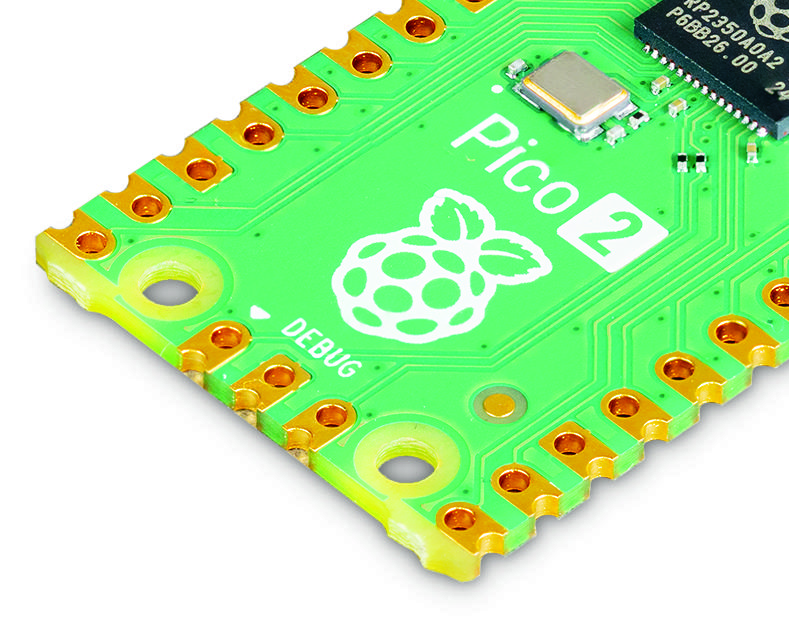
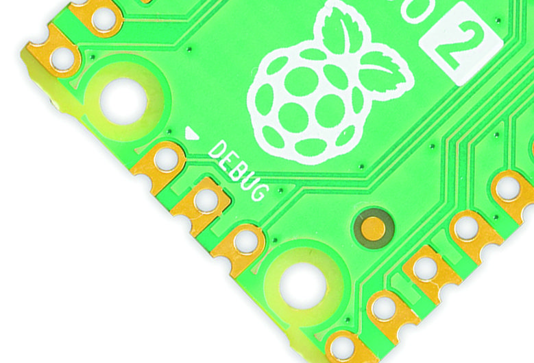
At the bottom of your Pico are three smaller gold pads with the word ‘DEBUG’ above them (Figure 1-6). These are designed for debugging, or finding errors, in programs running on the Pico, using a special tool called a debugger. You won’t need to use the debug header at first, but you may find it useful as you write larger and more complicated programs. On some Raspberry Pi Pico models, the debug pads are replaced by a small, three-pin connector.
Turn your Pico over and you’ll see the underside has writing on it (Figure 1-7). This printed text is known as a silk-screen layer, and labels each of the pins with its core function. You’ll see things like ‘GP0’ and ‘GP1’, ‘GND’, ‘RUN’, and ‘3V3’. If you ever forget which pin is which, these labels will tell you — but you won’t be able to see them when the Pico is pushed into a breadboard, so we’ve printed full pinout diagrams in this book for easier reference.
You might have noticed that not all the labels line up with their pins. The small holes at the top and bottom of the board are mounting holes, designed to allow you to fix your Pico to projects more permanently, using screws or nuts and bolts. Where the holes get in the way of the labelling, the labels are pushed further up or down the board: looking at the top-right. So ‘VBUS’ is the first pin on the left, ‘VSYS’ the second, and ‘GND’ the third.
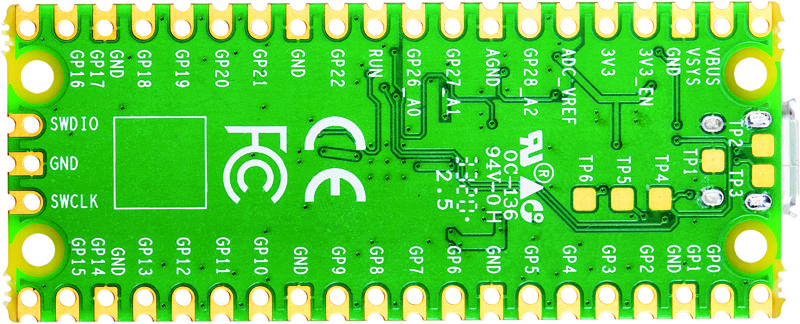
You’ll also see some flat, gold pads labelled with ‘TP’ and a number. These are test points, and are designed for engineers to quickly check that a Raspberry Pi Pico is working after it has been assembled at the factory — you won’t be using them yourself. Depending on the test pad, the engineer might use a multimeter or an oscilloscope to check that your Pico is working properly before it’s packaged up and shipped to you.
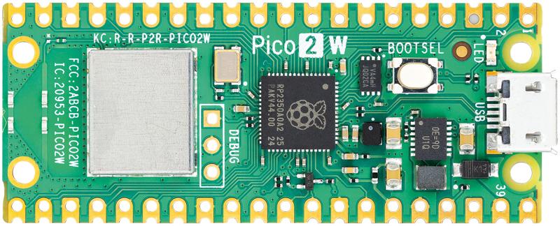
If you have a Raspberry Pi Pico 2 W, you’ll find another piece of hardware on the board: a silver metal rectangle (Figure 1-8). This is a shield for a wireless module, like the one on Raspberry Pi 4 and Raspberry Pi 5, which can be used to connect your Pico to a Wi-Fi network or to Bluetooth devices. It’s connected to a small antenna which sits at the very bottom of the board — which is why you’ll find the debug pads or connector closer to the middle of the board on Raspberry Pi Pico 2 W.
Soldering the headers
Look at a standard Raspberry Pi Pico-family board, and you’ll see it is completely flat. There are no metal pins like you’d find on the GPIO header of your Raspberry Pi or on the Pico-family boards with headers.
The easiest way to use a Pico is to attach it to a solderless breadboard —for that, you’ll need to attach pin headers. You’ll need a soldering iron with a stand, some solder, a cleaning sponge, your Pico, and two 20-pin 2.54 mm male header strips. You can use a solderless breadboard to make the process easier.
Although this section shows how to solder headers to an original Raspberry Pi Pico, the process is the same for a Pico 2.
Sometimes 2.54 mm headers are provided in strips longer than 20 pins. If yours are longer, just count 20 pins in from one end and look at the plastic between the 20th and 21st pins: you’ll see it has a small indentation at either side. This is a break point: if you have flush cutters, you can snip them easily. If not, put your thumbnails in the indentation with the headers in both your left and right hands and bend the strip. It will break cleanly, leaving you with a strip of exactly 20 pins. If the remaining header strip is longer than 20 pins, do the same again so you have two 20-pin strips.
Turn your Pico upside-down, so you can see the silk-screen pin numbers and test points on the bottom. Take one of the two header strips and push it gently into the pin holes on the left-hand side of your Pico. Make sure that it’s properly inserted in the holes, and not just resting in the castellations, and that all 20 pins are in place, then take the other header and insert it into the right-hand side. When you’ve finished, the plastic blocks on the pins should be pushed up against your Pico’s circuit board.
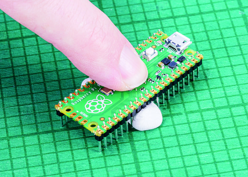
Pinch your Pico at the sides to hold both the circuit board and the two header strips. Don’t let go, or the headers will fall out! If you don’t have a breadboard yet, you’ll need a way to hold the headers in place while you’re soldering — and don’t use your fingers, or you’ll burn them. You can hold the headers in place with small alligator clips, or a small blob of Blu Tack or other sticky putty (Figure 1-9). Solder one pin, then check the alignment: if the pins are at an angle, melt the solder as you carefully adjust them to get everything lined up.
If you do have a breadboard, simply turn your breadboard and Pico upside down — remembering to keep the headers pinched — and use your Pico to gently push the headers into the holes on your breadboard, taking care to make sure the headers aren’t going in at an angle. Keep pushing until your Pico is lying flat, with the plastic blocks on the pin headers sandwiched between your Pico and your breadboard (Figure 1-10).
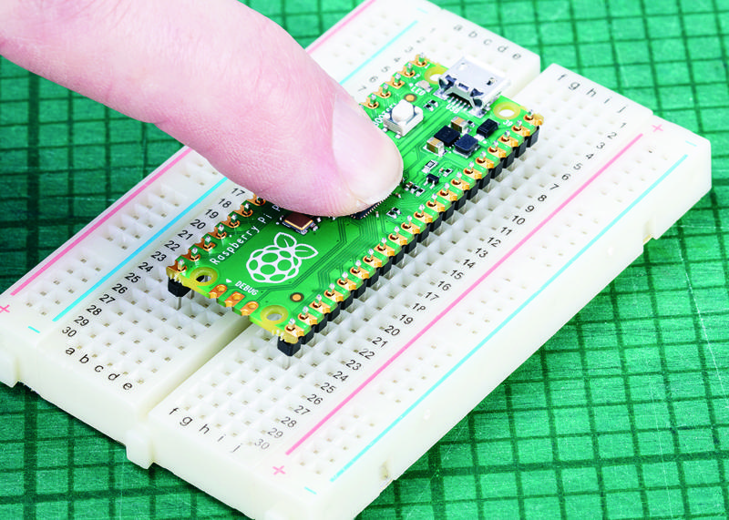
Look at the top of your Pico: you’ll see a small length of each pin is sticking up out of the pin holes. This is the part you’re going to solder — which means heating up both the pins and the pads on the Pico and melting a small amount of a special metal (solder) onto them.
Put your soldering iron in its stand, making sure the metal tip isn’t resting up against anything, and plug it in. It will take a few minutes for the tip of the iron to get hot; while you’re waiting, unroll a small length of solder — about twice as long as your index finger. You should be able to break the solder by pulling and twisting it; it’s a very soft metal.
If your soldering stand has a cleaning sponge, take the sponge to the sink and put a little bit of cold water (preferably distilled or deionized) on it so it softens. Squeeze the excess water out of the sponge, so it’s damp but not dripping, and put it back on the stand. If you’re using a cleaner made of coiled brass wire, you don’t need any water.
Pick up your soldering iron by the handle, making sure to keep the cable from catching on anything as you move it around. Hold it like a pencil, but make sure your fingers only ever touch the plastic or rubber handle area: the metal parts, even the shaft ahead of the actual iron tip, will be extremely hot and can burn you very quickly.
Before you begin soldering, clean the iron’s tip: brush it along your sponge or coiled wire cleaner. Take your length of solder, holding it at one end, and push the other end onto the tip of your iron: it should quickly melt into a blob. If it doesn’t, leave your soldering iron to heat up for longer — or try giving the tip another clean.
Putting a blob of solder on the tip is known as tinning the iron. The flux in the solder helps to burn off any oxidation still on the tip of the iron, and gets it ready. Wipe the iron on your sponge or cleaning wire again to clean off the excess solder; the tip should be left looking shiny and clean.
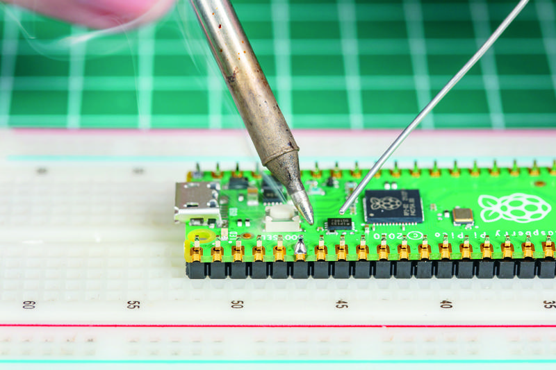
Put the iron back in the stand, where it should always be unless you’re actively using it, and move your Pico so it’s in front of you. Pick up the iron in one hand and the solder in the other. Press the tip of the iron against the pin closest to you, so that it’s touching both the vertical metal pin and the gold-coloured pad on your Pico at the same time (Figure 1-11).
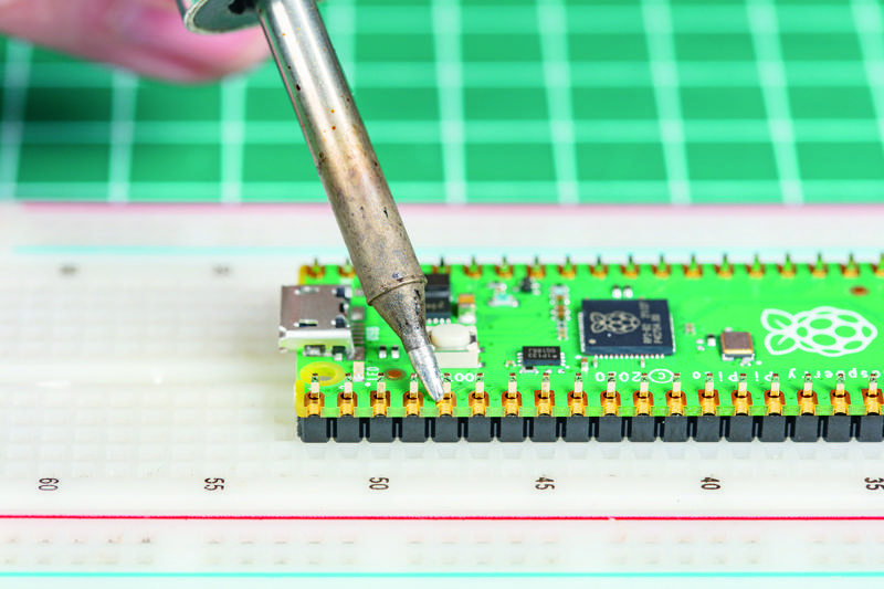
It’s important that the pin and the pad are both heated up, so keep your iron pressed against both while you count to three. When you’ve reached three, still keeping the iron in place, press the end of your length of solder gently against both the pin and pad but on the opposite side to your iron tip, as shown in Figure 1-12. Just like when you tinned the tip, the solder should melt quickly and begin to flow.
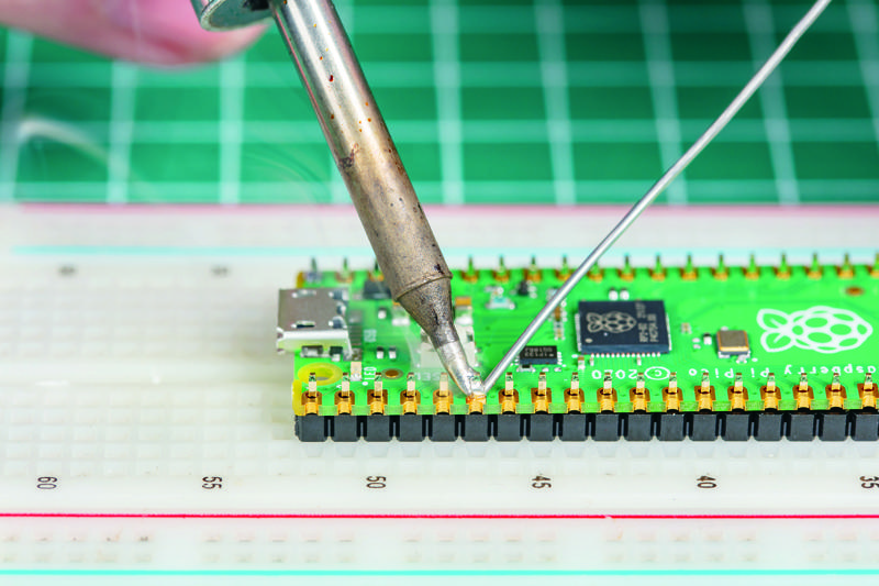
The solder will flow around the pin and the pad, but no further: that’s because your Pico’s circuit board is coated in a layer called solder resist which keeps the solder where it needs to be. Make sure not to use too much solder: a little goes a long way.
If you’re using Blu Tack or some other putty, solder the corner pins first to anchor the headers, then remove the putty before you solder any more. That way, you don’t have to worry about melting the putty as you solder.
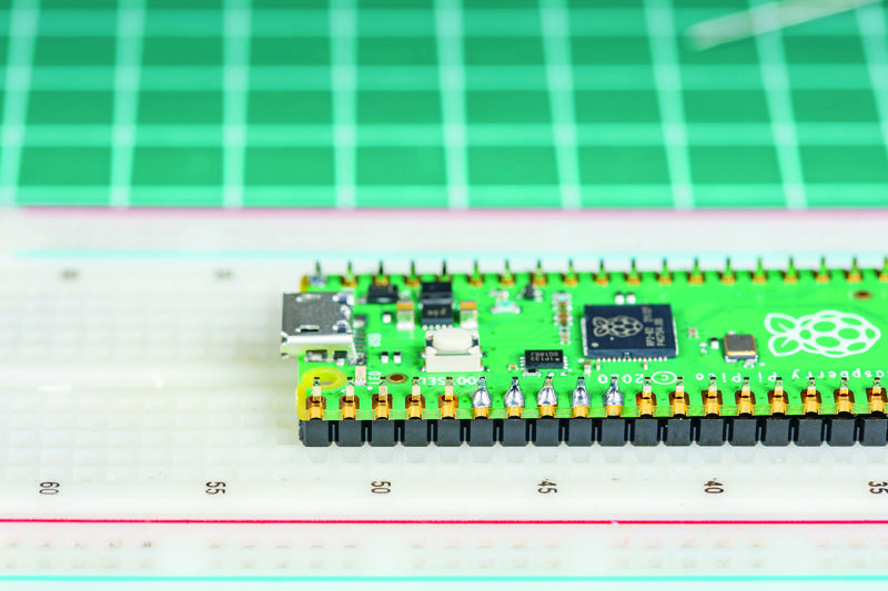
Pull the remaining part of your solder away from the joint, making sure to keep the iron in place. If you pull the iron away first, the solder will harden and you won’t be able to remove the piece in your hand; if that happens, just put the iron back in place to melt it again. Once the molten solder has spread around the pin and pad (Figure 1-13), which should only take a second or so, remove the soldering iron. Congratulations: you’ve soldered your first pin!
Clean the tip of your iron on your sponge or brass wire, and put it back in the stand. Pick up your Pico and look at your solder joint: it should fill the pad and rise up to meet the pin smoothly, looking a little like a volcano shape with the pin filling in the hole where the lava would be, as shown in Figure 1-14.
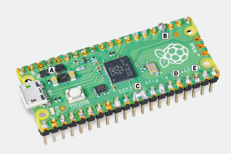
If the solder is too hot, it won’t flow well and you’ll get an overheated joint with some burnt flux (example A in Figure 1-15). This can be removed with a bit of careful scraping with the tip of a knife, or a toothbrush and a little 90% isopropyl alcohol.
On the other hand, if the solder is entirely covering the pin, as in example B in Figure 1-15, you used too much. That’s not necessarily going to cause a problem, though it doesn’t look very attractive: so long as none of the solder is touching any of the pins around it, it should still work. If it is touching other pins (as in example C of Figure 1-15), you’ve created a bridge which will cause a short circuit.
Again, bridges are easy to fix. First, try reflowing the solder on the joint you were making; if that doesn’t work, put your iron against the pin and pad at the other side of the bridge to flow some of it into the joint there. If there’s still far too much solder, you’ll need to remove the excess before you use your Pico: you can buy desoldering braid, which you press against the molten solder to wick the excess up, or a desoldering pump to physically suck the molten solder up.
If the solder is sticking to the pin but not sticking to the copper pad, as in example D in Figure 1-15, then the pad wasn’t heated up enough. Don’t worry, it’s easily fixed: take your soldering iron and place it where the pad and pin meet, making sure that it’s pressing against both this time. After a few seconds, the solder should reflow and make a good joint.
Another common mistake is too little solder: if you can still see copper pad, or there’s a gap between the pin and the pad which isn’t filled in with solder, you used too little (example E in Figure 1-15). Put the iron back on the pin and pad, count to three, and add a little more solder. Too little is always easier to fix than too much, so remember to take it easy with the solder!
Once you’re happy with the first pin, repeat the process for all 40 pins on your Pico — leaving the three-pin ‘DEBUG’ header at the bottom empty. Tip: solder the four corner pins first. Take your time, don’t rush, and remember that mistakes can always be fixed. Remember to clean your iron’s tip regularly during your soldering, and if you find things are getting difficult, melt some solder on it to re-tin the tip. Be sure to keep refreshing your length of solder, too: if it’s too short and your fingers are too close to the iron’s tip, you can burn yourself.
When you’re finished, and you’ve checked all the pins for good solder joints and to make sure they’re not bridged to any nearby pins, clean and tin the iron’s tip one last time before putting it back in the stand and unplugging it. Make sure to let the iron cool before you put it away: soldering irons can stay hot enough to burn you for a long time after they’ve been unplugged!
Finally, it’s time to wash your hands — and celebrate your new skill as a soldering supremo!
Installing MicroPython
Now that your Pico is ready to go (Figure 1-16), there’s only one thing left to do to get it ready: install MicroPython onto it. Start by plugging a micro USB cable into the micro USB port on your Pico — make sure it’s the right way up before gently pushing it in the rest of the way.
Hold down the ‘BOOTSEL’ button on the top of your Pico. Then, while still holding it down, connect the other end of the micro USB cable to one of the USB ports on your computer. Count to three, then let go of the button.
After a few more seconds you should see your Pico appear as a removable drive, as though you’d connected a USB flash drive or external hard drive.
On a Raspberry Pi, you’ll see a pop-up asking if you’d like to open the drive in the File Manager. Make sure Open in File Manager is selected and click OK.
On Windows, you may see an autoplay notification. You can click that and then choose Open Folder to View Files. Alternatively, you can open File Explorer, navigate to This PC, and double-click the RPI-RP2 (Pico 1 series) or RP2350 (Pico 2 series) drive to open it.
On an Apple Mac, it’s likely to quietly mount the drive without fanfare. Open the Finder and look for RPI-RP2 or RP2350 in the sidebar to the left of the Finder window. It’s likely to appear under Locations. If the sidebar is not visible, click View and select Show Sidebar.
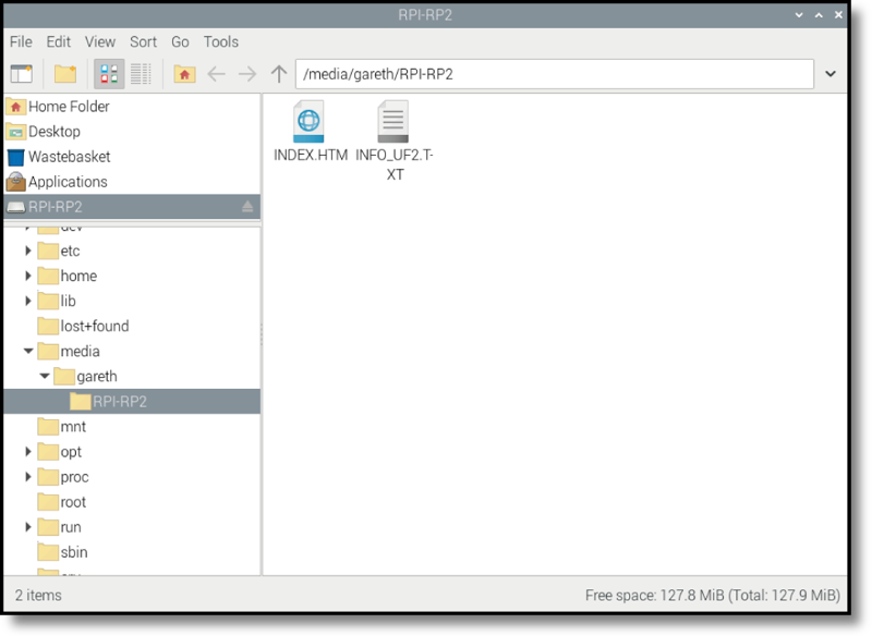
In the File Manager window, you’ll see two files on your Pico (Figure 1-17): INDEX.HTM and INFO_UF2.TXT. The second file contains information about your Pico, such as the version of the bootloader it’s currently running. The first file, INDEX.HTM, is a link to the Raspberry Pi Pico website. Double-click on this file or open your web browser and type rptl.io/microcontroller-docs into the address bar.
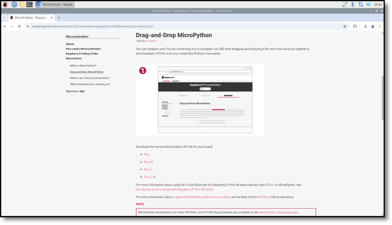
When the web page opens, you’ll see information about Raspberry Pi’s Pico-family boards. Click on the MicroPython box to go to the firmware download page. Scroll down to the section labelled Drag-and-Drop MicroPython, as shown in Figure 1-18, and find the link for the version of MicroPython for your board. There’s one for Raspberry Pi Pico and Pico H, another for Raspberry Pi Pico W and Pico WH, a third for Raspberry Pi Pico 2 and Pico 2 H, and a fourth for Raspberry Pi Pico 2 W and Pico 2 WH. Click on the link to download the appropriate UF2 file. If you accidentally download the wrong file, don’t worry; you can come back to the page at any time and flash new firmware onto your device using the same process.
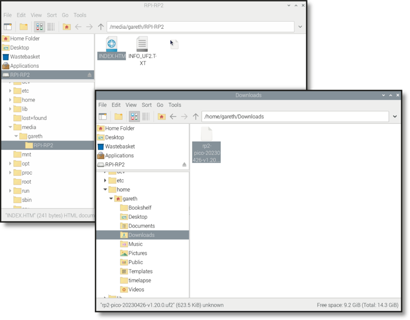
Open a new File Manager (Raspberry Pi), Windows Explorer, or macOS Finder window, then navigate to your Downloads folder and find the file you just downloaded. it will be called rp2-pico, rp2-pico-w, RPI_PICO2, or RPI_PICO2W followed by a date, some identifying text and numbers, along with the extension uf2.
Click and hold the mouse button on the UF2 file, then drag it to the other window that’s open on your Pico’s removable storage drive. Hover it over that window and let go of the mouse button to drop the file onto your Pico, as shown in Figure 1-19.
After a few seconds you’ll see your Pico drive window disappear from File Manager, Explorer, or Finder, and you may also see a warning that a drive was removed without being ejected. Don’t worry, that’s supposed to happen! When you dragged the MicroPython firmware file onto your Pico, you told it to flash the firmware onto its internal storage. To do that, your Pico switches out of the special mode you put it in with the ‘BOOTSEL’ button, flashes the new firmware, and then loads it — your Pico is now running MicroPython.
Congratulations: you’re now ready to get started with MicroPython on your Raspberry Pi Pico!
Writing and running code with ViperIDE
Connect your Pico to ViperIDE and write your first MicroPython programs — no software to install, no admin rights needed.
Your Pico is flashed with MicroPython and ready to go. Now you need a way to actually write code and send it to the board. That’s ViperIDE: it runs entirely in your browser, talks to your Pico over USB using a feature called WebSerial, and needs nothing installed on the computer. That matters in a lab full of Chromebooks and locked-down Macs where you can’t install anything anyway.
Go to viper-ide.org in Chrome or another Chromium-based browser (WebSerial doesn’t work in Safari or Firefox yet). You don’t need an account.
Connecting your Pico
Plug your Pico into your computer with a micro USB cable. In ViperIDE, look for the option to connect over USB/serial. Your browser will show a list of devices — pick the one that matches your Pico (it may show up as something like “USB Serial Device”). The first time, your browser will ask permission to talk to the device; allow it.
Once connected, you should see your Pico’s files in ViperIDE’s file manager, even if that list is empty right now.
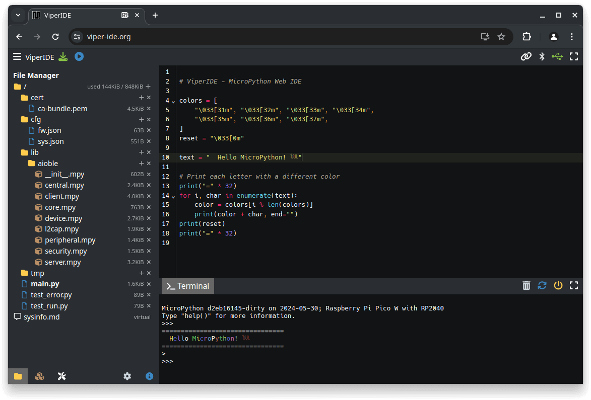
Screenshot: ViperIDE by Volodymyr Shymanskyy, MIT License.
Two ways to run code: the REPL and script files
ViperIDE gives you two different places to write code, and they behave differently.
The REPL (read-eval-print loop) is a live prompt connected directly to your Pico. Anything you type runs immediately, one line at a time, and nothing you type there is saved. It’s great for quick experiments and checking what a line of code actually does.
The editor is where you write a real program: multiple lines, saved as
a file on your Pico (usually main.py, which runs automatically every
time your Pico powers on). This is where your actual projects will live.
Your first program: Hello, World!
Click into the REPL and type:
print("Hello, world!")
Press Enter. Your Pico should immediately print the message back. That
print() function is how your program talks to you — you’ll use it
constantly, especially for figuring out what’s going wrong when something
doesn’t work.
Now try the editor instead. Create a new file, type the same line, and
save it to your Pico as main.py:
print("Hello, world!")
Click the blue ▶ (play) button near the ViperIDE logo, or press
F5. You should see the same output — but this time, the code stays on
your Pico. Unplug it, plug it back in, and it’ll print the message again
on its own, because main.py runs automatically on startup.
Loops and indentation
Typing the same print() line five times would work, but it’s tedious —
and if you wanted to change the message, you’d have to change it in five
places. A loop does the repetition for you:
for count in range(5):
    print("Message number", count)
Run that in the editor. You should see five lines of output, numbered 0 through 4 — not 1 through 5. MicroPython, like most programming languages, starts counting from zero.
Notice the indentation: the print() line is indented under the for
line. That indentation isn’t just for readability — it’s how MicroPython
knows which lines belong inside the loop. Everything indented the same
amount right after the for line runs once per loop; anything back at the
left margin runs only once, after the loop finishes.
Variables and conditionals
A variable stores a value so you can use it later, and change it:
favorite_number = 7

if favorite_number > 5:
    print("That's a big number!")
else:
    print("That's a small number!")
Run it, then change favorite_number to something less than 5 and run it
again. The if line asks a question — is favorite_number > 5? — and
MicroPython runs whichever indented block matches the answer.
You can chain more conditions with elif (“else if”):
favorite_number = 7

if favorite_number > 100:
    print("That's huge!")
elif favorite_number > 5:
    print("That's a big number!")
else:
    print("That's a small number!")
You now have the basic building blocks — printing, loops, variables, and conditionals — that every program in this pathway builds on. None of this needed your Pico’s hardware; you could have run all of it on ViperIDE’s Virtual Device. That changes starting next lesson, where these same building blocks start controlling real components.
Further reading
- ViperIDE — the tool itself
- How to write code for your Raspberry Pi Pico in your web browser with ViperIDE, Tom’s Hardware — a walkthrough of the same setup from a different angle
Physical computing
Learn about your Raspberry Pi Pico’s pins and the electronic components you can connect and control
When people think of ‘programming’ or ‘coding’, they’re usually — and naturally — thinking about software. Coding can be about more than just software, though: it can affect the real world through hardware. This is called physical computing. As the name suggests, physical computing is all about controlling things in the real world with your programs: hardware, rather than software. When you set the program on your washing machine, change the temperature on your programmable thermostat, or press a button at traffic lights to cross the road safely, you’re using physical computing.
These devices are typically controlled by a microcontroller very much like the one on your Raspberry Pi Pico-family device — and it’s entirely possible for you to create your own control systems by learning to take advantage of your Pico’s capabilities, just as easily as you learned to write software that runs on your Pico.
Your Pico’s pins
Your Pico talks to hardware through the series of pins along both its edges. Most work as programmable input/output (PIO) pins, meaning they can be programmed to act as either an input or an output, and have no preset purpose of their own until you assign one. Some pins have extra features and alternative modes for communicating with more complicated hardware; others have a specific purpose, providing connections for things like power.
Raspberry Pi Pico’s 40 pins are labelled on the underside of the board, with three also labelled with their numbers on the top of the board: Pin 1, Pin 2, and Pin 39. These top labels help you remember how the numbering works: Pin 1 is at the top-left as you look at the board from above, with the micro USB port to the upper side. Pin 20 is the bottom-left, Pin 21 the bottom-right, and Pin 39 one below the top-right with the unlabelled Pin 40 above it. The labelling on the underside is more thorough, but you won’t be able to see it when your Pico is plugged into a breadboard!
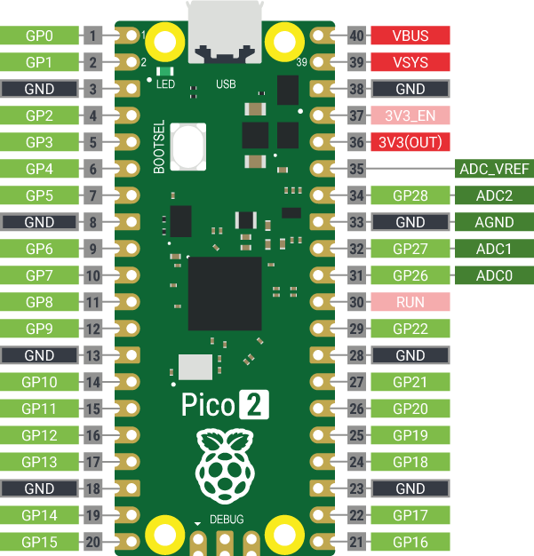
On the Raspberry Pi Pico, pins are usually referred to by their functions (see Figure 3-1) rather than by number. There are several categories of pin types, each of which has a particular function:
- 3V3(OUT) — 3.3 volts power — A source of 3.3V power generated from the VSYS input. This power supply can be switched off by shorting the pin above it (3V3_EN) to GND, which also switches your Pico off.
- VSYS — ~2-5 volts power — A pin directly connected to your Pico’s internal power supply, which cannot be switched off without also switching the Pico off.
- VBUS — 5 volts power — A source of 5V power taken from your Pico’s micro USB port, and used to power hardware which needs more than 3.3V. If you are connection the output of a component to your Pico’s GPIO pins, take care that the component’s output pins do not exceed 3.3V.
- GND — 0 volts ground — A ground connection, used to complete a circuit connected to a power source. Several GND pins are dotted around your Pico to make wiring easier.
- GPxx — General-purpose input/output pin number ‘xx’ — The GPIO pins available for your program, labelled GP0 through to GP28.
- GPxx_ADCx — General-purpose input/output pin number ‘xx’, with analogue input number ‘x’ — A GPIO pin which ends in ADC and a number can be used as an analogue input as well as a digital input or output — but not both at the same time.
- ADC_VREF — Analogue-to-digital converter (ADC) voltage reference — A special input pin which sets a reference voltage for any analogue inputs.
- AGND —ADC 0 volts ground — A special ground connection for use with the ADC_VREF pin.
- RUN — Enables or disables your Pico — The RUN pin is used to start and stop your Pico from another microcontroller or other controlling device.
Several of the GPIO pins have additional functions, which you’ll learn about later in the book. For a full pinout including these additional functions, see Appendix B, Pinout guide.
Electronic components
Your Pico is only part of what you’ll need to work with physical computing. You’ll also need some electrical components, the devices you’ll control from Pico’s GPIO pins. There are thousands of different components available, but most physical computing projects are made using the following common parts.
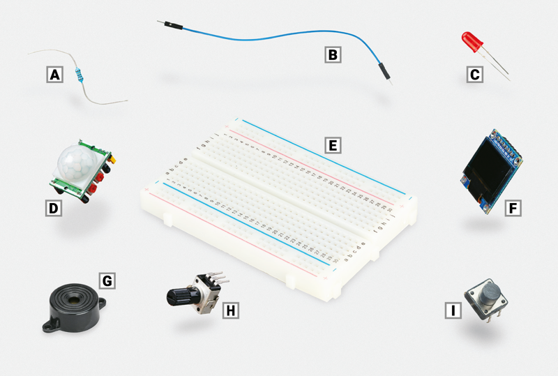
- Resistor (A) — these components control the flow of electrical current and are available in different values, measured using a unit called ohms (Ω). The higher the number of ohms, the more resistance is provided. For Pico physical computing projects, you’ll often use resistors rated at around 330Ω to protect LEDs from drawing too much current and damaging themselves or your Pico. You’ll need higher-value resistors, around 8.2 kΩ, for some projects in this book, but values as high as 20 kΩ are handy. Many suppliers sell packs of assorted values.
- Jumper wires (B) — also known as jumper leads, connect components to your Pico and, if you’re not using a breadboard, to each other. They are available in three versions: male-to-female (M2F); female-to-female (F2F), which can be used to connect individual components to your Pico if you’re not using a breadboard; and male-to-male (M2M), which is used to make connections from one part of a breadboard to another. Depending on your project, you may need all three types of jumper wire. If you’re using a breadboard, you can usually get away with just M2F and M2M jumper wires.
- Light-emitting diode (LED, C) — this is an output device which you can control directly from your program. An LED lights up when it’s powered on, and you’ll find them all over your house: from the small ones which let you know when you’ve left your washing machine switched on, to the large ones you might have lighting up your rooms. LEDs are available in a wide range of shapes, colours, and sizes, but not all are suitable for use with your Pico: avoid any which say they are designed for 5V or 12V power supplies.
- Passive infrared sensor (PIR, D) — this is one of a variety of input devices known as sensors, designed to report on changes in whatever they are monitoring. In the case of a PIR sensor, it monitors movement of people or animals: the sensor watches for movement in its field of view (determined by its plastic lens) and sends a signal when it detects a change. PIR sensors are commonly found on burglar alarms, to find people moving in the dark.
- Breadboard (E) — also known as a solderless breadboard, can make physical computing projects considerably easier. Rather than having a bunch of separate components which need to be connected with wires, a breadboard lets you insert components and have them connected through metal tracks which are hidden beneath its surface. Many breadboards also include sections for power distribution, making it even easier to build your circuits. You don’t need a breadboard to get started with physical computing, but it certainly helps.
- OLED display (F) — this is a screen which talks to your Pico over a special communication system such as the inter-integrated circuit (I2C) bus. Such a bus lets your Pico control the display panel, sending everything from writing to pictures for it to display. There are lots of types of display available, though a popular one — and the one found in this book — is based around the SSD1306 OLED driver, which supports both I2C and serial peripheral interface (SPI) interfaces. Note that some displays only use the I2C bus rather than SPI; they’ll still work with your Pico, but will only support the one bus and won’t work with the SPI example in this book.
- Piezoelectric buzzer (G) — also called a buzzer or a sounder, is another output device. Whereas an LED produces light, a buzzer produces a buzzing noise. Inside the buzzer’s plastic housing are a pair of metal plates. When active, these plates vibrate against each other to produce the buzzing sound. There are two types of buzzers: active buzzers and passive buzzers. Make sure to get an active buzzer, as these are the simplest to use.
- Potentiometer (H) — this is the sort of component you might find as a volume control on a music player, and can work as two different components. With two of its three legs connected, it acts as a variable resistor or varistor, a type of resistor which can be adjusted at any time by twisting the knob. With all three legs properly wired up, it becomes a voltage divider and outputs anything from 0V to the full voltage input depending on the position of the knob.
- Push-button switch (I) — this is the type of switch you might find on controllers for a game console. Commonly available with two or four legs — either type will work with your Pico — the push-button switch is an input device: you can tell your program to wait until you press it and then perform a task. A common variant is a latching switch: while a momentary push-button is only active when you’re holding it down, a latching switch — like a light switch — activates when you toggle it once, then stays active until you toggle it again.
Other common electrical components include motors, which need a special control board before they can be connected to your Pico, infrared sensors which detect movement, temperature and humidity sensors which can be used to predict the weather; and light-dependent resistors (LDRs) — input devices which operate like a reverse LED by detecting light.
Sellers all over the world provide components for physical computing with Raspberry Pi Pico, either as individual parts or in kits which provide everything you need to get started. To find sellers, visit rptl.io/products, click Raspberry Pi Pico 2 (or Raspberry Pi Pico 1 series), and click the Buy now button to see a list of Raspberry Pi partner online stores and approved resellers for your country or region.
To complete the projects in this book, you should have at least:
- A Raspberry Pi Pico-family device with male headers attached
- A micro USB cable
- A solderless breadboard
- A Raspberry Pi or other computer for programming
- Male-to-female (M2F) and male-to-male (M2M) jumper wires
- 3 × single-colour LEDs: red, green, and yellow or amber
- 1 × active piezoelectric buzzer
- 1 × 10 kΩ potentiometer, linear or logarithmic
- 3 × 330 Ω resistors and at least one 8.2 kΩ, 10 kΩ, and 20 kΩ resistor
- At least one HC-SR501 PIR sensor
- 1 × SSD1306 OLED module
- WS2812B RGB LEDs (or compatible)
You will also find it helpful to buy a cheap storage box with multiple compartments, so you can keep the components you’re not using in your project safe and tidy. If you can, try to find one that will also fit the breadboard — that way you can tidy everything away each time you’re done.
Reading resistor colour codes
Resistors come in a wide range of values, from zero-resistance versions which are effectively just pieces of wire to high-resistance versions the size of your leg. Very few of these resistors have their values printed on them in numbers. Instead, they use a special code (Figure 3-3) printed as coloured stripes or bands around the body of the resistor.
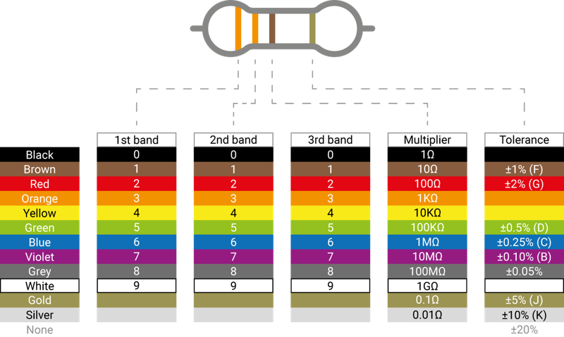
To read the value of a resistor, position it so the group of bands is to the left and the lone band is to the right. Starting from the first band, look its colour up in the ‘1st/2nd Band’ column of the table to get the first and second digits. This example has two orange bands, which both mean a value of ‘3’ for a total of ‘33’. If your resistor has four grouped bands instead of three, note down the value of the third band too (for five/six-band resistors, see rptl.io/5-6-band).
Moving onto the last grouped band — the third or fourth — look its colour up in the ‘Multiplier’ column. This tells you what you need to multiply your current number by to get the actual value of the resistor. This example has a brown band, which means ‘×101’. That may look confusing, but it’s simply scientific notation: ‘×101’ simply means ‘add one zero to the end of your number’. If it were blue, for ×106’, you would add six zeroes instead.
Taking 33 from the orange bands, plus the added zero from the brown band, gives us 330 — which is the value of the resistor, measured in ohms. The final band, the one on the right, is the tolerance of the resistor. This is simply how close to its rated value it is likely to be. Cheaper resistors might have a silver band, indicating a tolerance 10% higher or lower than its rating, or no last band at all, indicating a tolerance 20% higher or lower. The most expensive resistors have a grey band, indicating a tolerance within 0.05% of its rating. For hobbyist projects, accuracy isn’t that important: any tolerance will usually work fine.
If your resistor value goes above 1000 ohms (1000Ω), it is usually rated in kilohms (kΩ); if it goes above a million ohms, those are megohms (MΩ). A 2200Ω resistor would be written as 2.2 kΩ; a 2,200,000Ω resistor would be written as 2.2 MΩ.
Physical computing with Raspberry Pi Pico
Start connecting basic electronic components to Raspberry Pi Pico and writing programs to control and sense them
Raspberry Pi Pico and Pico 2, with their RP2040 or RP2350 microcontrollers, are designed with physical computing in mind. Their numerous general-purpose input/output (GPIO) pins let them talk to a range of components, allowing you to build up projects from lighting LEDs to recording data about the world around you.
Physical computing is no more difficult to learn than traditional computing: if you could follow the examples in the ViperIDE lesson, you’ll be able to build your own circuits and program them to interact with the real world.
Your first physical computing program: Hello, LED!
Just as printing ‘Hello, World’ to the screen is the usual first step in learning a programming language, making an LED light up is the traditional introduction to learning physical computing on a new platform. You can get started without any additional components, too: your Raspberry Pi Pico has a small LED, known as a surface-mount device (SMD) LED, on top.
Start by finding the LED: it’s the small rectangular component to the left of the micro USB port at the top of the board (Figure 4-1), marked ‘LED’.
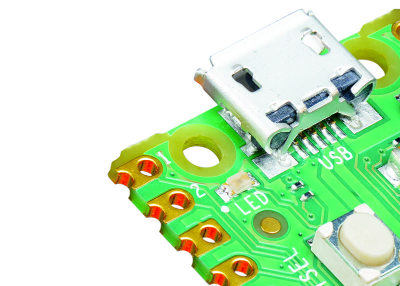
The on-board LED is connected to a GPIO pin (GP25 for Pico and Pico 2, but a GPIO on the wireless chip for Pico W and Pico 2 W) that is not broken out to a physical pin on the edge of your Pico. While you can’t connect external hardware to the pin, it can be treated just the same as any other GPIO pin within your programs, but must be referred to as "LED". It’s a simple way to add an output to your programs without needing any extra components.
Open ViperIDE and connect to your Pico — see the ViperIDE lesson for a refresher if you need one. Create a new file, then start your program with the following line:
import machine
This short line of code is key to working with MicroPython on your Pico. It loads, or imports, a collection of MicroPython code known as a library — in this case, the machine library. The machine library contains all the instructions MicroPython needs to communicate with the Pico and other MicroPython-compatible devices, extending the language for physical computing. Without this line, you won’t be able to control any of your Pico’s GPIO pins — and you won’t be able to make the on-board LED light up.
The machine library exposes what is known as an application programming interface (API). The name sounds complicated, but describes exactly what it does: it provides a way for your program, or the application, to communicate with the Pico via an interface.
The next line of your program provides an example of the machine library’s API:
led_onboard = machine.Pin("LED", machine.Pin.OUT)
This line defines an object called led_onboard, which offers a friendly name you can use to refer to the on-board LED later in your program. It’s technically possible to use any name here, but it’s best to stick with names which describe the variable’s purpose, to make the program easier to read and understand.
The second part of the line calls the Pin function in the machine library. This function, as its name suggests, is designed for handling your Pico’s GPIO pins. At the moment, none of the GPIO pins — including the on-board LED pin — know what they’re supposed to be doing. The first argument, "LED", tells the Pin function to use the GPIO assigned to the on-board LED, which means you don’t need to remember its pin number. The second, machine.Pin.OUT, tells Pico the pin should be used as an output rather than an input.
That line alone is enough to set the pin up, but it won’t light the LED. To do that, you need to tell your Pico to actually turn the pin on. Type the following code on the next line:
led_onboard.value(1)
This line is also using the machine library’s API. Your earlier line created the object led_onboard as an output on the on-board LED pin; this line takes the object and sets its value to 1 for ‘on’. It could also set the value to 0, for ‘off’.
Click the Run button and save the program on your Pico as Blink.py. You’ll see the LED light up. Congratulations: you’ve written your first physical computing program!
You’ll notice, however, that the LED stays lit. That’s because your program tells the Pico to turn it on, but never tells it to turn it off. You can add another line at the bottom of your program:
led_onboard.value(0)
Run the program this time, though, and the LED never seems to light up. That’s because your Pico works very, very quickly — much faster than you can see with the naked eye. The LED is lighting up, but for such a short time that it appears to remain dark. To fix that, you need to slow your program down by introducing a delay.
Go back to the top of your program: click to move your cursor to the end of the first line and press ENTER to insert a new second line. On this line, type:
import time
Like import machine, this line imports a new library into MicroPython: the time library. This library handles everything to do with time, from measuring it to inserting delays into your programs.
Click on the end of the line led_onboard.value(1), then press ENTER to insert a new line. Type:
time.sleep(5)
This calls the sleep function from the time library, which makes your program pause for the number of seconds you typed: in this case, five seconds.
Click the Run button again. This time you’ll see the on-board LED on your Pico light up, stay lit for five seconds — try counting along — and go out again.
Finally, it’s time to make the LED blink. To do that, you’ll need to create a loop. Rewrite your program so it matches the one below:
import machine
import time

led_onboard = machine.Pin("LED", machine.Pin.OUT)

while True:
    led_onboard.value(1)
    time.sleep(5)
    led_onboard.value(0)
    time.sleep(5)
Remember that the lines inside the loop need to be indented by four spaces, so MicroPython knows they form the loop. Click the Run icon again, and you’ll see the LED switch on for five seconds, switch off for five seconds, and switch on again, constantly repeating in an infinite loop. The LED will continue to flash until you stop the program (or press Ctrl-D to reset your Pico).
There’s another way to handle the same job, too: using a toggle, rather than setting the LED’s output to 0 or 1 explicitly. Delete the last four lines of your program and replace them so it looks like this:
import machine
import time

led_onboard = machine.Pin("LED", machine.Pin.OUT)

while True:
    led_onboard.toggle()
    time.sleep(5)
Run your program again. You’ll see the same activity as before: the on-board LED will light up for five seconds, then go out for five seconds, then light up again in an infinite loop. This time, though, your program is two lines shorter: you’ve optimised it. Available on all digital output pins, toggle() simply switches between on and off: if the pin is currently on, toggle() switches it off; if it’s off, toggle() switches it on.
Using a breadboard
The next projects in this chapter will be much easier to complete if you use a solderless breadboard (Figure 4-2) to hold the components and make the electrical connections.
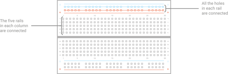
A breadboard is covered with holes which are spaced 2.54mm apart to match most components. Under these holes are metal strips (terminals) which act like invisible jumper wires. These run in columns on the board, with most boards having a gap down the middle to split them in two halves. Many breadboards also have letters going up the left side and numbers on the top and bottom. These allow you to find a particular hole: A1 is the bottom-left, B1 is the hole just above it, while B2 is one hole to the right. A1 is connected to B1 by the hidden metal strips, but no number hole is ever connected to a different number hole unless you add a jumper wire.
Larger breadboards also have strips of holes along the top and bottom, typically marked with red and black or red and blue stripes. These are the power rails, and are designed to make wiring easier: you can connect a single wire from your Pico’s ground pin to one of the power rails — typically marked with a blue or black stripe and a minus symbol — to provide a common ground for lots of components on the breadboard, and you can do the same if your circuit needs 3.3V or 5V power.
Adding electronic components to a breadboard is simple: just line their leads (the sticky-out metal parts) up with the holes and gently push until the component is in place. For connections you need to make beyond those the breadboard makes for you, you can use male-to-male (M2M) jumper wires; for connections from the breadboard to components not installed in the breadboard, use male-to-female (M2F) jumper wires.
Push your Pico into the breadboard so it straddles the middle gap and the micro USB port is at the edge of the board (see Figure 4-3). Pins 1 and 40 should be in the breadboard column marked with a 1, if your breadboard is numbered. Before pushing your Pico down, make sure the header pins are all properly positioned — if you bend a pin, it can be difficult to straighten it again without it breaking.

Gently push the Pico down until the plastic parts of the header pins are touching the breadboard. This means the metal parts of the header pins are fully inserted and making good electrical contact with the breadboard.
Next steps: an external LED
So far, you’ve been working with your Pico on its own — running MicroPython programs on its RP2040 or RP2350 microcontroller and toggling the on-board LED on and off. Microcontrollers are usually used with external components, though — and your Pico is no exception.
For this project, you’ll need a breadboard, male-to-male (M2M) jumper wires, an LED, and a 330 Ω resistor — or as close to 330 Ω as you have available. If you don’t have a breadboard, you can use female-to-female (F2F) jumper wires, but the circuit will be fragile and easy to break.
Hold the LED in your fingers: you’ll see one of its leads is longer than the other. The longer lead is known as the anode, and represents the positive side of the circuit; the shorter lead is the cathode, and represents the negative side. The anode needs to be connected to one of your Pico’s GPIO pins via the resistor; the cathode needs to be connected to a ground pin.
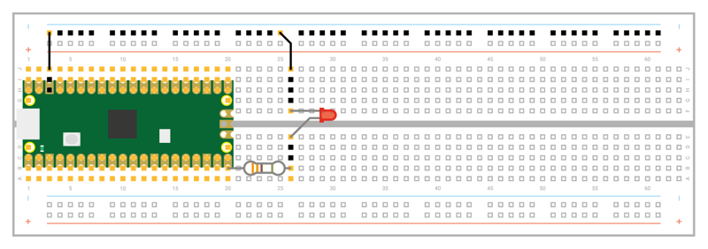
With your Pico unplugged from USB, start by connecting the resistor: take either end and insert it into the breadboard in the same column as your Pico’s GP15 pin at the bottom-right — if you’re using a numbered breadboard with your Pico inserted at the edge, this should be column 20. Push the other end into a free column further down the breadboard — we’re using column 26.
Take the LED, and push the longer leg — the anode — into the same column as the end of the resistor. Push the shorter leg — the cathode — into the same column but across the centre gap in the breadboard, so it’s lined up but not electrically connected to the longer leg except through the LED itself. Finally, insert a male-to-male (M2M) jumper wire into the same column as the shorter leg of the LED, then either connect it directly to one of your Pico’s ground pins (via another hole in its column) or to the negative side of your breadboard’s power rail. If you connect it to the power rail, finish the circuit by connecting the rail to one of your Pico’s ground pins. Your finished circuit should look like Figure 4-4. Connect your Pico to your Raspberry Pi or computer.
Controlling an external LED in MicroPython is no different to controlling your Pico’s internal LED: only the pin number changes. If you closed ViperIDE, reopen it and load your Blink.py program from earlier in the chapter. Find the line:
led_onboard = machine.Pin("LED", machine.Pin.OUT)
Edit the pin number, changing it from the string "LED" — the pin connected to your Pico’s internal LED — to 15, the pin to which you connected the external LED. Also edit the name you created: you’re not using the on-board LED anymore, so have it say led_external instead. You’ll also have to change the name elsewhere in the program, until it looks like this:
import machine
import time

led_external = machine.Pin(15, machine.Pin.OUT)

while True:
    led_external.toggle()
    time.sleep(5)
You don’t really need to change the name in the program: it would run just the same if you’d left it at led_onboard, as it’s only the pin number which truly matters. When you come back to the program later, though, it would be very confusing to have an object named led_onboard which lights up an external LED — try to get into the habit of making sure your names match their purpose!
Inputs: reading a button
Outputs like LEDs are one thing, but the ‘input/output’ part of ‘GPIO’ means you can use pins as inputs too. For this project, you’ll need a breadboard, male-to-male jumper wires, and a push-button switch. If you don’t have a breadboard, you can use female-to-female (F2F) jumper wires, but the button will be much harder to press without accidentally breaking the circuit.
With your Pico unplugged from USB, remove any other components from your breadboard except your Pico, and begin by adding the push-button switch. If your push-button has only two legs, make sure they’re in different-numbered columns on the breadboard somewhere to the right of you Pico. If it has four legs, turn it so the flat sides (the sides the legs don’t stick out from) are aligned in the same numbered column, but also straddling the centre divide of the breadboard (as seen in Figure 4-5).
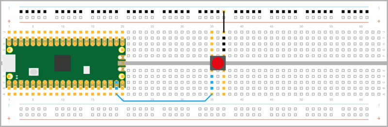
Connect the ground or negative power rail of your breadboard to one of your Pico’s GND pins, Pin 38, and from there to one of the legs of the switch; then connect the other leg to pin GP14 on your Pico — it’s the one just to the left of the pin you used for the LED project, and should be in column 19 of your breadboard.
If you’re using a push-button with four legs, your circuit will only work if you use the correct pair of legs: the legs are connected in pairs, so you need to either use the two legs on the same side of the centre divide or diagonally opposite legs.
Connect your Pico to USB again. Next, open ViperIDE, if you haven’t already, and start a new program with the usual line:
import machine
Next, set up a pin as an input, rather than an output:
button = machine.Pin(14, machine.Pin.IN, machine.Pin.PULL_UP)
This works in the same way as your LED projects: an object called button is created, which includes the pin number — GP14, in this case — and configures it as an input with the internal resistor set to pull-up. Creating the object, though, doesn’t mean it will do anything by itself — just as creating the LED objects earlier didn’t make the LEDs light up.
To actually read the button, you need to use the machine API again — this time using the value function to read, rather than set, the value of the pin. Type the following line:
print(button.value())
Click the Run icon and save your program as Button.py — remembering to make sure it saves on your Pico. Your program will print out a single number: the value of the input on GP14. Because the input is using a pull-up resistor, this value will be 1 — letting you know the button isn’t pushed.
Hold down the button with your finger, and press the Run icon again. This time, you’ll see the value 0 printed to the Terminal: pushing the button has completed the circuit and changed the value read from the pin.
To read the button continuously, you’ll need to add a loop to your program. Edit the program so it reads as below:
import machine
import time

button = machine.Pin(14, machine.Pin.IN, machine.Pin.PULL_UP)

while True:
    if button.value() == 0:
        print("You pressed the button!")
        time.sleep(2)
Click the Run button again. Nothing will happen until you press the button; when you do, you’ll see a message printed to the Terminal. The delay, meanwhile, is important: your Pico runs a lot faster than you can read, and without the delay even a brief button press will print hundreds of messages!
You’ll see the message print every time you press the button. If you hold the button down for longer than the two-second delay, it will print the message every two seconds until you let go of the button.
Inputs and outputs: putting it all together
Most circuits have more than one component, which is why your Pico has so many GPIO pins. It’s time to put everything you’ve learned together to build a more complex circuit: a device which switches an LED on and off with a button.
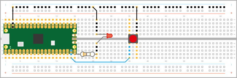
This circuit combines the previous two, which used pin GP15 to drive the external LED, and GP14 to read the button; now rebuild your circuit so the LED and the button are on the breadboard at the same time, still connected to GP15 and GP14 (see Figure 4-6). Remember the LED’s current-limiting resistor and to disconnect from USB while you’re building the circuit!
Start a new program, and import these two libraries:
import machine
import time
Next, set up both the input and output pins:
led_external = machine.Pin(15, machine.Pin.OUT)
button = machine.Pin(14, machine.Pin.IN, machine.Pin.PULL_UP)
Then create a loop which reads the button:
while True:
    if button.value() == 0:
Rather than printing a message to the Terminal, this time you’ll toggle the output pin (and the LED connected to it) based on the value of the input pin. Type the following, remembering it will need to be indented by eight spaces — which your editor should indent automatically after you press Enter on the line above:
        led_external.value(1)
        time.sleep(2)
That’s enough to turn the LED on, but you’ll also need to turn it off again when the button isn’t being pressed. Add the following new line, using the BACKSPACE key to delete four of the eight spaces — meaning the line will not be part of the if statement, but will form part of the infinite loop:
led_external.value(0)
Your finished program should look like this:
import machine
import time

led_external = machine.Pin(15, machine.Pin.OUT)
button = machine.Pin(14, machine.Pin.IN, machine.Pin.PULL_UP)

while True:
    if button.value() == 0:
        led_external.value(1)
        time.sleep(2)
    led_external.value(0)
Save the program as Switch.py on your Pico and click Run. At first, nothing will happen; push the button, and you’ll see the LED light up. Let go of the button; after two seconds, the LED will go out until you press the button again.
Congratulations: you’ve built your first circuit which controls one pin based on the input from another — a building block for bigger things!
Traffic light controller
Create your own mini pedestrian crossing system with multiple LEDs and a push-button
Microcontrollers can be found in almost all the electronic items you use on a daily basis — including traffic lights. A traffic light controller is a specially-built system which changes the lights on a timer, watches for pedestrians looking to cross, and can even adjust the timing of the lights depending on how much traffic there is — talking to nearby traffic light systems to ensure the whole traffic network keeps flowing smoothly.
While building a large-scale traffic management system is a pretty advanced project, it’s simplicity itself to build a miniature simulator powered by your Pico-family device. With this project, you’ll see how to control multiple LEDs, set different timings, and how to monitor a push-button input while the rest of the program continues to run using a technique known as interrupts.
For this project, you’ll need your Pico; a breadboard; a red, yellow (or amber), and green LED; three 330 Ω resistors; an active piezoelectric buzzer; and a selection of male-to-male (M2M) jumper wires. You’ll also need a micro USB cable to connect your Pico to your computer.
A simple traffic light
Disconnect your Pico from USB, and build the traffic light system shown in Figure 5-1. Take your red LED and insert it into the breadboard so it straddles the centre divide. Use one 330 Ω resistor, and a jumper wire if you need to make a longer connection, to connect the longer leg — the anode — of the LED to the pin at the bottom-right of your Pico as seen from the top with the micro USB cable leftmost, GP15. If you’re using a numbered breadboard and have your Pico inserted as shown, this will be column 20.
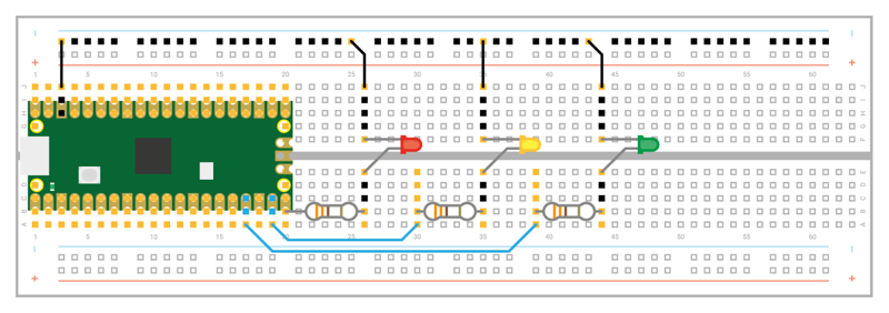
Take a jumper wire and connect the shorter leg — the cathode — of the red LED to your breadboard’s ground rail. Take another, and connect the ground rail to one of your Pico’s ground (GND) pins — in Figure 5-1, we’ve used the ground pin on column three of the breadboard.
You’ve now got one LED connected to your Pico, but a real traffic light has at least three in all: a red light to tell the traffic to stop, amber or yellow to tell the traffic the light is about to change, and green to tell the traffic it can go again.
Take your amber or yellow LED and wire it to your Pico in the same way as the red LED, making sure the shorter leg connected to the ground rail of the breadboard. This time, though, wire the longer leg — via the 330 Ω resistor — to the pin next to the one to which you wired the red LED, GP14.
Finally, take the green LED and wire it up the same way again — remembering the 330 Ω resistor — to pin GP13. This isn’t the pin right next to pin GP14, though — that pin is a ground (GND) pin, which you can see if you look closely at your Pico: the ground pins all have a square shape to their pads, while the other pins are round.
When you’ve finished, your circuit should match Figure 5-1: a red, a yellow or amber, and a green LED, all wired to different GPIO pins on your Pico via individual 330 Ω resistors and connected to a shared ground pin via your breadboard’s ground rail.
To program your traffic lights, connect your Pico to ViperIDE. Create a new program, and start by importing the machine library so you can control your Pico’s GPIO pins:
import machine
You’ll also need to import the time library, so you can add delays between the lights going on and off:
import time
As with any program using your Pico’s GPIO pins, you’ll need to set each pin up before you can control it:
led_red = machine.Pin(15, machine.Pin.OUT)
led_amber = machine.Pin(14, machine.Pin.OUT)
led_green = machine.Pin(13, machine.Pin.OUT)
These lines set pins GP15, GP14, and GP13 up as outputs, and each is given a descriptive name to make it easier to read the code: led, so you know the pins control an LED, and then the colour of the LED.
Real traffic lights don’t run through once and stop — they keep going, even when there’s no traffic there and everyone’s asleep. So that your program does the same, you’ll need to set up an infinite loop:
while True:
You’ll need to indent all the lines beneath this by four spaces, so MicroPython knows they form part of the loop; your editor should automatically indent the next line for you when you press Enter.
    led_red.value(1)
    time.sleep(5)
    led_amber.value(1)
    time.sleep(2)
    led_red.value(0)
    led_amber.value(0)
    led_green.value(1)
    time.sleep(5)
    led_green.value(0)
    led_amber.value(1)
    time.sleep(5)
    led_amber.value(0)
Save the program to your Pico as Traffic_Lights.py and click the Run icon. Watch the LEDs: red lights up first, telling traffic to stop; next, amber comes on to warn drivers the lights are about to change; then both switch off and green comes on to let traffic know it can pass; then green turns off and amber comes on to warn drivers the lights are about to change again; finally, amber turns off — and the loop restarts from the beginning, with red coming on.
The pattern will loop until you stop the program, because it forms an infinite loop. It’s based on the traffic light pattern used in real-world traffic control systems in the UK and Ireland, but sped up — giving cars just five seconds to pass through the lights wouldn’t let the traffic flow very freely!
Real traffic lights aren’t just there for road vehicles, though: they are also there to protect pedestrians, giving them an opportunity to cross a busy road safely. In the UK, the most common type of these lights are known as pedestrian-operated user-friendly intelligent crossings or puffin crossings.
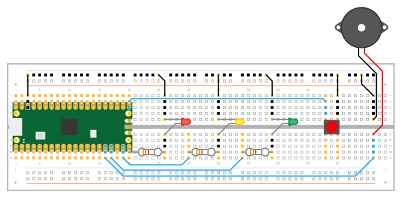
To turn your traffic lights into a puffin crossing, you’ll need two things: a push-button switch, so the pedestrian can ask the lights to let them cross the road; and a buzzer, so the pedestrian knows when it’s their turn to cross. Wire those into your breadboard as in Figure 5-2, with the switch wired to pin GP16 and the ground rail of your breadboard, and the buzzer wired to pin GP12 and the breadboard’s ground rail. Disconnect the Pico from USB while you build this.
If you run your program again, you’ll find the button and buzzer do nothing. That’s because you haven’t yet told your program how to use them. Go back to the lines where you initialised your LEDs and add two lines below:
button = machine.Pin(16, machine.Pin.IN, machine.Pin.PULL_UP)
buzzer = machine.Pin(12, machine.Pin.OUT)
This sets the button on pin GP16 up as an input, and the buzzer on pin GP12 as an output. Remember, your Raspberry Pi Pico has built-in programmable resistors for its inputs, which we are setting to pull-up mode for the projects in this book. This means that the pin’s voltage is pulled up to 3.3V (and its logic level is 1), unless it is connected to a GND pin (in which case its logic level will be 0 until disconnected).
Next, you need a way for your program to constantly monitor the value of the button. Previously, all your programs have worked step-by-step through a list of instructions — only ever doing one thing at a time. Your traffic light program is no different: as it runs, MicroPython walks through your instructions step-by-step, turning the LEDs on and off.
For a basic set of traffic lights, that’s enough; for a puffin crossing, though, your program needs to be able to record whether the button has been pressed in a way that doesn’t interrupt the traffic lights. To make that work, you’ll need a new approach: interrupt requests (IRQs).
The name sounds complex, but it’s simple: imagine you’re reading a book, page by page, and someone comes up to you and asks you a question. That person is performing an interrupt request: asking you to stop what you’re doing, answer their question, then letting you go back to reading your book.
A MicroPython interrupt request works in the same way: it allows something, in this case the press of a push-button switch, to interrupt the main program. To set up an interrupt, you need two things: the interrupt itself, and a handler or callback function**. Start with the handler first by adding the following lines to your program:
button_pressed = False

def btn_handler(pin):
    global button_pressed
    if not button_pressed:
        button_pressed = True
The first line creates a new variable to track whether the button has been pressed or not and sets it to False — meaning when the program starts, the button hasn’t yet been pushed. The next section defines the handler for your interrupt: when the interrupt is requested, the three indented lines will run. There’s no loop here, so the code will only run once — but if you press the button again, the code will run again.
The first of the indented lines turns the button_pressed variable into a global variable. The variables you’ve been working with prior to this are known as local variables, and only work in one section of your program; a global variable works everywhere, meaning one function can change the value and another can check to see if it has been changed even if they’re running in two separate sections of your program.
The next line checks to see if code has already run, by checking the state of the button_pressed variable. If it’s been set to True , because the button has already been pressed, the next line won’t run; only if it’s set to False , and hasn’t already been pushed, will the final line run to set the variable to True .
If you were to run your program now, the button wouldn’t do anything. That’s because you have a handler, but no trigger : pressing the button doesn’t make the interrupt request, and the handler never runs. To fix that, you need to add a new line to your program:
button.irq(trigger=machine.Pin.IRQ_FALLING, handler=btn_handler)
The trigger tells your Pico what it should be looking for as a valid signal to interrupt what it’s doing; the handler, which you defined earlier in your program, is the code which runs after the interrupt is triggered.
In this program your trigger is IRQ_FALLING: this triggers the interrupt when the pin’s value falls from high — its default state, thanks to the built-in pull-up resistor — to low, when the button connected to GND is pushed. A trigger of IRQ_RISING would do the opposite: trigger the interrupt when the pin goes from low to high. In the case of your circuit, IRQ_FALLING triggers as soon as the button is pushed; IRQ_RISING triggers only when the button is released.
Click the Run button now. You’ll see the traffic lights carry on their pattern exactly as before, with no delay or pauses. If you press the button, though, nothing will happen — because you haven’t added the code to actually react to the button yet.
Go to the start of your main loop, and add the following code directly underneath the line while True: — remembering to pay attention to the nested indentation, and deleting any indentation your editor added when it’s no longer required:
if button_pressed == True:
    led_red.value(1)
    for i in range(20):
        buzzer.value(1)
        time.sleep(0.05)
        buzzer.value(0)
        time.sleep(0.2)
    button_pressed = False
This chunk of code checks the button_pressed global variable to see if the push-button switch has been pressed at any time since the loop last ran. If it has, as reported by the button-reading handler you made earlier, it begins running a section of code which starts by turning the red LED on to stop traffic and then beeps the buzzer 20 times — letting the pedestrian know it’s time to cross.
Finally, the last line reset the button_pressed variable back to False — so the next time the loop runs it won’t trigger the pedestrian crossing code unless the button has been pushed again.
Your program should now look like this:
import machine
import time

led_red = machine.Pin(15, machine.Pin.OUT)
led_amber = machine.Pin(14, machine.Pin.OUT)
led_green = machine.Pin(13, machine.Pin.OUT)
button = machine.Pin(16, machine.Pin.IN, machine.Pin.PULL_UP)
buzzer = machine.Pin(12, machine.Pin.OUT)

button_pressed = False

def btn_handler(pin):
    global button_pressed
    if not button_pressed:
        button_pressed = True

button.irq(trigger=machine.Pin.IRQ_FALLING, handler=btn_handler)

while True:
    if button_pressed == True:
        led_red.value(1)
        for i in range(20):
            buzzer.value(1)
            time.sleep(0.05)
            buzzer.value(0)
            time.sleep(0.2)
        button_pressed = False
    led_red.value(1)
    time.sleep(5)
    led_amber.value(1)
    time.sleep(2)
    led_red.value(0)
    led_amber.value(0)
    led_green.value(1)
    time.sleep(5)
    led_green.value(0)
    led_amber.value(1)
    time.sleep(5)
    led_amber.value(0)
Click the Run icon. At first, the program will run as normal: the traffic lights will go on and off in the usual pattern. Press the push-button switch: if the program is currently in the middle of its loop, nothing will happen until it reaches the end and loops back around again — at which point the light will go red and the buzzer will beep to let you know it’s safe to cross the road.
The conditional section of code for crossing the road runs before the code you wrote earlier for turning the lights on and off in a cyclic pattern: after it’s finished, the pattern will begin as usual with the red LED staying lit for a further five seconds on top of the time it was lit while the buzzer was going. This mimics how a real puffin crossing works: the red light remains lit even after the buzzer has stopped sounding, so anyone who started to cross the road while the buzzer was going has time to reach the other side before the traffic is allowed to go.
Let the traffic lights loop through their cycle a few more times, then press the button again to trigger another crossing. Congratulations: you’ve built your own puffin crossing!