Appendix C
Appendix C: Programmable I/O
A tour of Programmable I/O, the Pico's trick for implementing custom hardware protocols
In this appendix, we look at code that looks very different from the code we’ve dealt with in the rest of this pathway. That’s because we’ll be dealing with things at a low level. Most of the time, MicroPython hides the complexities of how things work on the microcontroller. When we do something like:
print("hello")
…we don’t have to worry about the way the microcontroller stores the letters, or the format in which they get sent to the serial terminal, or the number of clock cycles the serial terminal takes. This is all handled in the background. However, when we get to Programmable Input and Output (PIO), we need to deal with things at a much lower level.
We’re going to go on a whistle-stop tour of PIO and introduce some advanced topics so you can get an idea of what’s going on, and hopefully understand how PIO on Pico offers some real advantages over the options you’ll find on other microcontrollers.
However, understanding all the low-level data manipulation required to create PIO programs takes time to fully get your head around, so don’t worry if it seems a little opaque. If you’re interested in tackling this low-level programming, then we’ll give you the knowledge to get started and point you in the right direction to continue your journey. If you’re more interested in working at a higher level and would rather leave the low-level wrangling to others, we’ll show you how to use PIO programs.
Data in and data out
Throughout this pathway, we’ve looked at ways of controlling the pins on your Pico using MicroPython. We can switch them on and off, take inputs, and even send data using the dedicated SPI and I2C controllers. However, what if we want to connect a device that doesn’t communicate in SPI or I2C? What about a device with its own special protocol?
There are a couple of ways to do this. On most MicroPython devices, you need to do a process called bit banging where you implement the protocol in MicroPython and turn pins on or off in the right order to send data.
There are three downsides to this. The first is that it’s slow. MicroPython does some things really well, but it doesn’t run as fast as natively compiled code.
The second is that we have to juggle this with the rest of our code that is running on the microcontroller.
The third is that some timing-critical code can be hard to implement reliably. Fast protocols often require that things happen at very precise times, and with MicroPython we can be quite precise, but if you’re trying to transfer megabits a second, you need things to happen every millisecond or possibly every few hundred nanoseconds. That’s hard to do (reliably) in MicroPython.
Pico has a solution to this: Programmable I/O. There are some extra, really stripped-back processing cores that can run simple programs to control the I/O pins. You can’t program these cores with MicroPython — you must use a special language just for them — but you can program them from MicroPython. Here’s an example (you’ll need to wire an LED to GP15 with a resistor as shown in “Next steps: an external LED”):
from rp2 import PIO, StateMachine, asm_pio
import machine
import time

@asm_pio(set_init=PIO.OUT_LOW)
def quarter_bright():
    set(pins, 0) [2]
    set(pins, 1)

@asm_pio(set_init=PIO.OUT_LOW)
def half_bright():
    set(pins, 0)
    set(pins, 1)

@asm_pio(set_init=PIO.OUT_HIGH)
def full_bright():
    set(pins, 1)

led = machine.Pin(15, machine.Pin.OUT)
sm1 = StateMachine(1, quarter_bright, freq=10000, set_base=led)
sm2 = StateMachine(2, half_bright, freq=10000, set_base=led)
sm3 = StateMachine(3, full_bright, freq=10000, set_base=led)

while(True):
    sm1.active(1)
    time.sleep(1)
    sm1.active(0)

    sm2.active(1)
    time.sleep(1)
    sm2.active(0)

    sm3.active(1)
    time.sleep(1)
    sm3.active(0)
There are three methods here that all look a little strange; they set the LED to quarter, half, and full brightness. The reason they look a little strange is because they’re written in a special language for the PIO system of Pico. You can probably guess what they do — flick the LED on and off very quickly in a similar way to how we used PWM. The instruction set(pins, 0) turns a GPIO pin off and set(pins, 1) turns the GPIO pin on.
Each of the three methods has a descriptor above it that tells MicroPython to treat it as a PIO program and not a normal method. These descriptors can also take parameters that influence the behaviour of the programs. In these cases, we’ve used the set_init parameter to tell the PIO whether the GPIO pin should start off being low or high.
Each of these methods — which are really mini programs that run on the PIO state machines — loops continuously. So, for example, half_bright will constantly turn the LED on and off so that it spends half its time off and half its time on. full_bright will similarly loop, but since the only instruction is to turn the LED on, this doesn’t actually change anything.
The slightly unusual one here is quarter_bright. Each PIO instruction takes exactly one clock cycle to run (the length of a clock cycle can be changed by setting the frequency, as we’ll see later). However, we can add a number between 1 and 31 in square brackets after an instruction, and this tells the PIO state machine to delay execution by this number of clock cycles before running the next instruction. In quarter_bright, then, the two set instructions each take one clock cycle, and the delay takes two clock cycles, so the total loop takes four clock cycles. In the first line, the set instruction takes one cycle and the delay takes two, so the GPIO pin is off for three of these four cycles. This makes the LED a quarter as bright as if it were on constantly.
Once you’ve got your PIO program, you need to load it into a state machine. Since we have three programs, we need to load them into three different state machines (there are eight you can use, numbered 0–7). You can load a PIO program with a line like this:
sm1 = StateMachine(1, quarter_bright, freq=10000, set_base=led)
The parameters here are:
- The state machine number
- The PIO program to load
- The frequency (which must be between 2000 and 125000000)
- The GPIO pin that the state machine manipulates
There are some additional parameters you’ll see in other programs that we don’t need here.
Once you’ve created your state machine, you can start and stop it using the active method with 1 (to start) or 0 (to stop). In our loop, we cycle through the three different state machines.
A real example
The previous example was a little contrived, so let’s look at a way of using PIO with a real example. WS2812B LEDs (sometimes known as NeoPixels) are a type of light that contains three LEDs (one red, one green, and one blue) and a small microcontroller. They’re controlled by a single data wire with a timing-dependent protocol that’s hard to bit-bang.
Wiring your LED strip is simple, as shown in Figure C-1. Depending on the manufacturer of your LED strip, you may have the wires already connected, you may have a socket that you can push header wires in, or you may need to solder them on yourself.
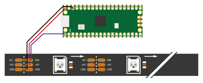
One thing you need to be aware of is the potential current draw. While you can add an almost endless series of NeoPixels to your Pico, there’s a limit to how much power you can get out of the 5V pin on Pico. Here, we’ll use eight LEDs, which is perfectly safe, but if you want to use many more than this, you need to understand the limitations and may need to add a separate power supply. You can cut a longer strip to length, and there should be cut lines between the LEDs to show you where to cut. There’s a good discussion of the various issues at hsmag.cc/neopixelpower.
Now we’ve got the LEDs wired up, let’s look at how to control it with PIO:
import array, time
from machine import Pin
import rp2
from rp2 import PIO, StateMachine, asm_pio

# Configure the number of WS2812 LEDs.
NUM_LEDS = 8

@asm_pio(sideset_init=PIO.OUT_LOW, out_shiftdir=PIO.SHIFT_LEFT,
         autopull=True, pull_thresh=24)
def ws2812():
    T1 = 2
    T2 = 5
    T3 = 3
    label("bitloop")
    out(x, 1)             .side(0) [T3 - 1]
    jmp(not_x, "do_zero") .side(1) [T1 - 1]
    jmp("bitloop")        .side(1) [T2 - 1]
    label("do_zero")
    nop()                 .side(0) [T2 - 1]

# Create a StateMachine with the ws2812 code and output on Pin(0).
sm = StateMachine(0, ws2812, freq=8000000, sideset_base=Pin(0))

# Start the StateMachine, it will wait for data on its FIFO.
sm.active(1)
The basic way that this works is that 800,000 bits of data are sent per second (notice that the frequency is 8000000 and each cycle of the program is 10 clock cycles). Every bit of data is a pulse — a short pulse indicating a 0 and a long pulse indicating a 1. A big difference between this and our previous program is that MicroPython needs to be able to send data to this PIO program.
There are two stages for data coming into the state machine. The first is a bit of memory called a First In, First Out queue (or FIFO). This is what our main Python program sends data to. The second is the Output Shift Register (OSR). This is where the out() instruction fetches data from. The two are linked by pull instructions which take data from the FIFO and put it in the OSR. However, since our program is set up with autopull enabled with a threshold of 24, each time we’ve read 24 bits from the OSR, it will be reloaded from the FIFO.
The instruction out(x,1) takes one bit of data from the OSR and places it in a variable called x (there are only two available variables in PIO: x and y).
The jmp instruction tells the code to move directly to a particular label, but it can have a condition. The instruction jmp(not_x, "do_zero") tells the code to move to do_zero if the value of x is 0 (or, in logical terms, if not_x is true, and not_x is the opposite of x — in PIO-level speak, 0 is false and any other number is true).
There’s a bit of jmp spaghetti that is mostly there to ensure that the timings are consistent because the loop has to take exactly the same number of cycles every iteration to keep the timing of the protocol in line.
The one aspect we’ve been ignoring here is the .side() bits. These are similar to set() but they take place at the same time as another instruction. This means that out(x,1) takes place as .side(0) is setting the value of the sideset pin to 0.
Phew, that’s quite a bit going on for such a small program. Now we’ve got it active, let’s look at how to use it. Add the following MicroPython code under the preceding code to send data to a PIO program.
# Display a pattern on the LEDs via an array of LED RGB values.
ar = array.array("I", [0 for _ in range(NUM_LEDS)])

print("blue")
for j in range(0, 255):
    for i in range(NUM_LEDS):
        ar[i] = j
    sm.put(ar,8)
    time.sleep_ms(10)

print("red")
for j in range(0, 255):
    for i in range(NUM_LEDS):
        ar[i] = j<<8
    sm.put(ar,8)
    time.sleep_ms(10)

print("green")
for j in range(0, 255):
    for i in range(NUM_LEDS):
        ar[i] = j<<16
    sm.put(ar,8)
    time.sleep_ms(10)

print("white")
for j in range(0, 255):
    for i in range(NUM_LEDS):
        ar[i] = (j<<16) + (j<<8) + j
    sm.put(ar,8)
    time.sleep_ms(10)
Here we keep track of an array called ar that holds the data we want our LEDs to have (we’ll look at why we created the array this way in a little while). Each number in the array contains the data for all three colours on a single light. The format is a little strange as it’s in binary. One thing about working with PIO is that you often need to work with individual bits of data. Each bit of data is a 1 or 0, and numbers can be built up in this way, so the number 2 in base 10 (as we call the normal numbers we’re used to using) is 10 in binary. 3 in base 10 is 11 in binary. The largest number in eight bits of binary is 11111111, or 255 in base 10. We won’t go too deep into binary here, but if you want to find out more, you can try the Binary Hero project here: hsmag.cc/binaryhero.
To make matters a little more confusing, we’re actually storing three numbers in a single number. This is because in MicroPython, whole numbers are stored in 32 bits, but we only need eight bits for each number. There’s a little free space at the end as we really only need 24 bits, but that’s OK.
The first eight bits are the blue values, the next eight bits are red, and the final eight bits are green. The maximum number you can store in eight bits is 255, so each LED has 255 levels of brightness. We can do this using the bit shift operator <<. This adds a certain number of 0s to the end of a number, so if we want our LED to be at level 1 brightness in red, green, and blue, we start with each value being 1, then shift them the appropriate number of bits. For green, we have:
1 << 16 = 10000000000000000
For red we have:
1 << 8 = 100000000
And for blue, we don’t need to shift the bits at all, so we just have 1. If we add all these together, we get the following (if we add the preceding bits to make it a 24-bit number):
000000010000000100000001
The rightmost eight bits are the blue, the next eight bits are red, and the leftmost eight bits are green. The part that may seem a bit confusing is this line from the top of the code you just added:
ar = array.array("I", [0 for _ in range(NUM_LEDS)])
This creates an array which has I as the first value, and then a 0 for every LED. The reason there’s an I at the start is that it tells MicroPython that we’re using a series of 32-bit values. However, we only want 24 bits of this sent to the PIO for each value, so we tell the put command to remove eight bits with:
sm.put(ar,8)
All the instructions
The language used for PIO state machines is very sparse, so there are only a small number of instructions. In addition to the ones we’ve looked at, you can use:
in()— moves between 1 and 32 bits into the state machine (similar, but opposite toout()).push()— sends data to the memory that links the state machine and the main MicroPython program.pull()— gets data from the chunk of memory that links the state machine and the main MicroPython program. We haven’t used it here, because by includingautopull=Truein our program, this happens automatically when we useout().mov()— moves data between two locations (such as between thexandyvariables or a register like OSR).irq()— controls interrupts. These are used if you need to trigger a particular thing to run on the MicroPython side of your program.wait()— pauses until something happens (such as a I/O pin changes to a set value or an interrupt happens).
Although there are only a small number of possible instructions, it’s possible to implement a huge range of communications protocols. Most of the instructions are for moving data about in some form. If you need to prepare the data in any particular way, such as manipulating the colours you want your LEDs to be, this should be done in your main MicroPython program rather than the PIO program.
You can find more information on how to use these, and the full range of options for PIO in MicroPython on Raspberry Pi Pico in the Pico Python SDK document — and a complete reference to how PIO works in the RP2040 and RP2350 databooks. These are available at rptl.io/microcontroller-docs.