← MicroPython on Raspberry Pi Pico
Lesson 4
Physical computing with Raspberry Pi Pico
Start connecting basic electronic components to Raspberry Pi Pico and writing programs to control and sense them
Raspberry Pi Pico and Pico 2, with their RP2040 or RP2350 microcontrollers, are designed with physical computing in mind. Their numerous general-purpose input/output (GPIO) pins let them talk to a range of components, allowing you to build up projects from lighting LEDs to recording data about the world around you.
Physical computing is no more difficult to learn than traditional computing: if you could follow the examples in the ViperIDE lesson, you’ll be able to build your own circuits and program them to interact with the real world.
Your first physical computing program: Hello, LED!
Just as printing ‘Hello, World’ to the screen is the usual first step in learning a programming language, making an LED light up is the traditional introduction to learning physical computing on a new platform. You can get started without any additional components, too: your Raspberry Pi Pico has a small LED, known as a surface-mount device (SMD) LED, on top.
Start by finding the LED: it’s the small rectangular component to the left of the micro USB port at the top of the board (Figure 4-1), marked ‘LED’.
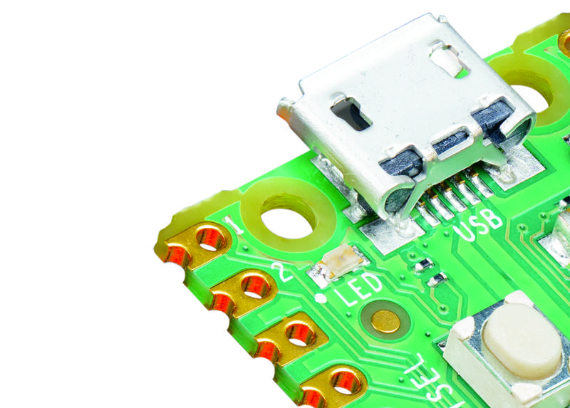
The on-board LED is connected to a GPIO pin (GP25 for Pico and Pico 2, but a GPIO on the wireless chip for Pico W and Pico 2 W) that is not broken out to a physical pin on the edge of your Pico. While you can’t connect external hardware to the pin, it can be treated just the same as any other GPIO pin within your programs, but must be referred to as "LED". It’s a simple way to add an output to your programs without needing any extra components.
Open ViperIDE and connect to your Pico — see the ViperIDE lesson for a refresher if you need one. Create a new file, then start your program with the following line:
import machine
This short line of code is key to working with MicroPython on your Pico. It loads, or imports, a collection of MicroPython code known as a library — in this case, the machine library. The machine library contains all the instructions MicroPython needs to communicate with the Pico and other MicroPython-compatible devices, extending the language for physical computing. Without this line, you won’t be able to control any of your Pico’s GPIO pins — and you won’t be able to make the on-board LED light up.
The machine library exposes what is known as an application programming interface (API). The name sounds complicated, but describes exactly what it does: it provides a way for your program, or the application, to communicate with the Pico via an interface.
The next line of your program provides an example of the machine library’s API:
led_onboard = machine.Pin("LED", machine.Pin.OUT)
This line defines an object called led_onboard, which offers a friendly name you can use to refer to the on-board LED later in your program. It’s technically possible to use any name here, but it’s best to stick with names which describe the variable’s purpose, to make the program easier to read and understand.
The second part of the line calls the Pin function in the machine library. This function, as its name suggests, is designed for handling your Pico’s GPIO pins. At the moment, none of the GPIO pins — including the on-board LED pin — know what they’re supposed to be doing. The first argument, "LED", tells the Pin function to use the GPIO assigned to the on-board LED, which means you don’t need to remember its pin number. The second, machine.Pin.OUT, tells Pico the pin should be used as an output rather than an input.
That line alone is enough to set the pin up, but it won’t light the LED. To do that, you need to tell your Pico to actually turn the pin on. Type the following code on the next line:
led_onboard.value(1)
This line is also using the machine library’s API. Your earlier line created the object led_onboard as an output on the on-board LED pin; this line takes the object and sets its value to 1 for ‘on’. It could also set the value to 0, for ‘off’.
Click the Run button and save the program on your Pico as Blink.py. You’ll see the LED light up. Congratulations: you’ve written your first physical computing program!
You’ll notice, however, that the LED stays lit. That’s because your program tells the Pico to turn it on, but never tells it to turn it off. You can add another line at the bottom of your program:
led_onboard.value(0)
Run the program this time, though, and the LED never seems to light up. That’s because your Pico works very, very quickly — much faster than you can see with the naked eye. The LED is lighting up, but for such a short time that it appears to remain dark. To fix that, you need to slow your program down by introducing a delay.
Go back to the top of your program: click to move your cursor to the end of the first line and press ENTER to insert a new second line. On this line, type:
import time
Like import machine, this line imports a new library into MicroPython: the time library. This library handles everything to do with time, from measuring it to inserting delays into your programs.
Click on the end of the line led_onboard.value(1), then press ENTER to insert a new line. Type:
time.sleep(5)
This calls the sleep function from the time library, which makes your program pause for the number of seconds you typed: in this case, five seconds.
Click the Run button again. This time you’ll see the on-board LED on your Pico light up, stay lit for five seconds — try counting along — and go out again.
Finally, it’s time to make the LED blink. To do that, you’ll need to create a loop. Rewrite your program so it matches the one below:
import machine
import time

led_onboard = machine.Pin("LED", machine.Pin.OUT)

while True:
    led_onboard.value(1)
    time.sleep(5)
    led_onboard.value(0)
    time.sleep(5)
Remember that the lines inside the loop need to be indented by four spaces, so MicroPython knows they form the loop. Click the Run icon again, and you’ll see the LED switch on for five seconds, switch off for five seconds, and switch on again, constantly repeating in an infinite loop. The LED will continue to flash until you stop the program (or press Ctrl-D to reset your Pico).
There’s another way to handle the same job, too: using a toggle, rather than setting the LED’s output to 0 or 1 explicitly. Delete the last four lines of your program and replace them so it looks like this:
import machine
import time

led_onboard = machine.Pin("LED", machine.Pin.OUT)

while True:
    led_onboard.toggle()
    time.sleep(5)
Run your program again. You’ll see the same activity as before: the on-board LED will light up for five seconds, then go out for five seconds, then light up again in an infinite loop. This time, though, your program is two lines shorter: you’ve optimised it. Available on all digital output pins, toggle() simply switches between on and off: if the pin is currently on, toggle() switches it off; if it’s off, toggle() switches it on.
Using a breadboard
The next projects in this chapter will be much easier to complete if you use a solderless breadboard (Figure 4-2) to hold the components and make the electrical connections.
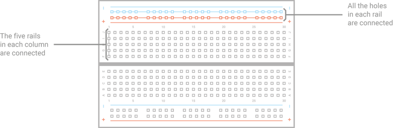
A breadboard is covered with holes which are spaced 2.54mm apart to match most components. Under these holes are metal strips (terminals) which act like invisible jumper wires. These run in columns on the board, with most boards having a gap down the middle to split them in two halves. Many breadboards also have letters going up the left side and numbers on the top and bottom. These allow you to find a particular hole: A1 is the bottom-left, B1 is the hole just above it, while B2 is one hole to the right. A1 is connected to B1 by the hidden metal strips, but no number hole is ever connected to a different number hole unless you add a jumper wire.
Larger breadboards also have strips of holes along the top and bottom, typically marked with red and black or red and blue stripes. These are the power rails, and are designed to make wiring easier: you can connect a single wire from your Pico’s ground pin to one of the power rails — typically marked with a blue or black stripe and a minus symbol — to provide a common ground for lots of components on the breadboard, and you can do the same if your circuit needs 3.3V or 5V power.
Adding electronic components to a breadboard is simple: just line their leads (the sticky-out metal parts) up with the holes and gently push until the component is in place. For connections you need to make beyond those the breadboard makes for you, you can use male-to-male (M2M) jumper wires; for connections from the breadboard to components not installed in the breadboard, use male-to-female (M2F) jumper wires.
Push your Pico into the breadboard so it straddles the middle gap and the micro USB port is at the edge of the board (see Figure 4-3). Pins 1 and 40 should be in the breadboard column marked with a 1, if your breadboard is numbered. Before pushing your Pico down, make sure the header pins are all properly positioned — if you bend a pin, it can be difficult to straighten it again without it breaking.

Gently push the Pico down until the plastic parts of the header pins are touching the breadboard. This means the metal parts of the header pins are fully inserted and making good electrical contact with the breadboard.
Next steps: an external LED
So far, you’ve been working with your Pico on its own — running MicroPython programs on its RP2040 or RP2350 microcontroller and toggling the on-board LED on and off. Microcontrollers are usually used with external components, though — and your Pico is no exception.
For this project, you’ll need a breadboard, male-to-male (M2M) jumper wires, an LED, and a 330 Ω resistor — or as close to 330 Ω as you have available. If you don’t have a breadboard, you can use female-to-female (F2F) jumper wires, but the circuit will be fragile and easy to break.
Hold the LED in your fingers: you’ll see one of its leads is longer than the other. The longer lead is known as the anode, and represents the positive side of the circuit; the shorter lead is the cathode, and represents the negative side. The anode needs to be connected to one of your Pico’s GPIO pins via the resistor; the cathode needs to be connected to a ground pin.
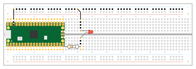
With your Pico unplugged from USB, start by connecting the resistor: take either end and insert it into the breadboard in the same column as your Pico’s GP15 pin at the bottom-right — if you’re using a numbered breadboard with your Pico inserted at the edge, this should be column 20. Push the other end into a free column further down the breadboard — we’re using column 26.
Take the LED, and push the longer leg — the anode — into the same column as the end of the resistor. Push the shorter leg — the cathode — into the same column but across the centre gap in the breadboard, so it’s lined up but not electrically connected to the longer leg except through the LED itself. Finally, insert a male-to-male (M2M) jumper wire into the same column as the shorter leg of the LED, then either connect it directly to one of your Pico’s ground pins (via another hole in its column) or to the negative side of your breadboard’s power rail. If you connect it to the power rail, finish the circuit by connecting the rail to one of your Pico’s ground pins. Your finished circuit should look like Figure 4-4. Connect your Pico to your Raspberry Pi or computer.
Controlling an external LED in MicroPython is no different to controlling your Pico’s internal LED: only the pin number changes. If you closed ViperIDE, reopen it and load your Blink.py program from earlier in the chapter. Find the line:
led_onboard = machine.Pin("LED", machine.Pin.OUT)
Edit the pin number, changing it from the string "LED" — the pin connected to your Pico’s internal LED — to 15, the pin to which you connected the external LED. Also edit the name you created: you’re not using the on-board LED anymore, so have it say led_external instead. You’ll also have to change the name elsewhere in the program, until it looks like this:
import machine
import time

led_external = machine.Pin(15, machine.Pin.OUT)

while True:
    led_external.toggle()
    time.sleep(5)
You don’t really need to change the name in the program: it would run just the same if you’d left it at led_onboard, as it’s only the pin number which truly matters. When you come back to the program later, though, it would be very confusing to have an object named led_onboard which lights up an external LED — try to get into the habit of making sure your names match their purpose!
Inputs: reading a button
Outputs like LEDs are one thing, but the ‘input/output’ part of ‘GPIO’ means you can use pins as inputs too. For this project, you’ll need a breadboard, male-to-male jumper wires, and a push-button switch. If you don’t have a breadboard, you can use female-to-female (F2F) jumper wires, but the button will be much harder to press without accidentally breaking the circuit.
With your Pico unplugged from USB, remove any other components from your breadboard except your Pico, and begin by adding the push-button switch. If your push-button has only two legs, make sure they’re in different-numbered columns on the breadboard somewhere to the right of you Pico. If it has four legs, turn it so the flat sides (the sides the legs don’t stick out from) are aligned in the same numbered column, but also straddling the centre divide of the breadboard (as seen in Figure 4-5).
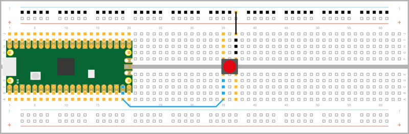
Connect the ground or negative power rail of your breadboard to one of your Pico’s GND pins, Pin 38, and from there to one of the legs of the switch; then connect the other leg to pin GP14 on your Pico — it’s the one just to the left of the pin you used for the LED project, and should be in column 19 of your breadboard.
If you’re using a push-button with four legs, your circuit will only work if you use the correct pair of legs: the legs are connected in pairs, so you need to either use the two legs on the same side of the centre divide or diagonally opposite legs.
Connect your Pico to USB again. Next, open ViperIDE, if you haven’t already, and start a new program with the usual line:
import machine
Next, set up a pin as an input, rather than an output:
button = machine.Pin(14, machine.Pin.IN, machine.Pin.PULL_UP)
This works in the same way as your LED projects: an object called button is created, which includes the pin number — GP14, in this case — and configures it as an input with the internal resistor set to pull-up. Creating the object, though, doesn’t mean it will do anything by itself — just as creating the LED objects earlier didn’t make the LEDs light up.
To actually read the button, you need to use the machine API again — this time using the value function to read, rather than set, the value of the pin. Type the following line:
print(button.value())
Click the Run icon and save your program as Button.py — remembering to make sure it saves on your Pico. Your program will print out a single number: the value of the input on GP14. Because the input is using a pull-up resistor, this value will be 1 — letting you know the button isn’t pushed.
Hold down the button with your finger, and press the Run icon again. This time, you’ll see the value 0 printed to the Terminal: pushing the button has completed the circuit and changed the value read from the pin.
To read the button continuously, you’ll need to add a loop to your program. Edit the program so it reads as below:
import machine
import time

button = machine.Pin(14, machine.Pin.IN, machine.Pin.PULL_UP)

while True:
    if button.value() == 0:
        print("You pressed the button!")
        time.sleep(2)
Click the Run button again. Nothing will happen until you press the button; when you do, you’ll see a message printed to the Terminal. The delay, meanwhile, is important: your Pico runs a lot faster than you can read, and without the delay even a brief button press will print hundreds of messages!
You’ll see the message print every time you press the button. If you hold the button down for longer than the two-second delay, it will print the message every two seconds until you let go of the button.
Inputs and outputs: putting it all together
Most circuits have more than one component, which is why your Pico has so many GPIO pins. It’s time to put everything you’ve learned together to build a more complex circuit: a device which switches an LED on and off with a button.
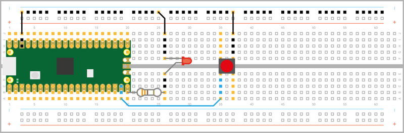
This circuit combines the previous two, which used pin GP15 to drive the external LED, and GP14 to read the button; now rebuild your circuit so the LED and the button are on the breadboard at the same time, still connected to GP15 and GP14 (see Figure 4-6). Remember the LED’s current-limiting resistor and to disconnect from USB while you’re building the circuit!
Start a new program, and import these two libraries:
import machine
import time
Next, set up both the input and output pins:
led_external = machine.Pin(15, machine.Pin.OUT)
button = machine.Pin(14, machine.Pin.IN, machine.Pin.PULL_UP)
Then create a loop which reads the button:
while True:
    if button.value() == 0:
Rather than printing a message to the Terminal, this time you’ll toggle the output pin (and the LED connected to it) based on the value of the input pin. Type the following, remembering it will need to be indented by eight spaces — which your editor should indent automatically after you press Enter on the line above:
        led_external.value(1)
        time.sleep(2)
That’s enough to turn the LED on, but you’ll also need to turn it off again when the button isn’t being pressed. Add the following new line, using the BACKSPACE key to delete four of the eight spaces — meaning the line will not be part of the if statement, but will form part of the infinite loop:
led_external.value(0)
Your finished program should look like this:
import machine
import time

led_external = machine.Pin(15, machine.Pin.OUT)
button = machine.Pin(14, machine.Pin.IN, machine.Pin.PULL_UP)

while True:
    if button.value() == 0:
        led_external.value(1)
        time.sleep(2)
    led_external.value(0)
Save the program as Switch.py on your Pico and click Run. At first, nothing will happen; push the button, and you’ll see the LED light up. Let go of the button; after two seconds, the LED will go out until you press the button again.
Congratulations: you’ve built your first circuit which controls one pin based on the input from another — a building block for bigger things!