Lesson 8
Chapter 8: Temperature gauge
Use your Raspberry Pi Pico’s built-in ADC to convert analogue inputs, and also to read its internal temperature sensor
Use your Raspberry Pi Pico’s built-in ADC to convert analogue inputs, and also to read its internal temperature sensor
In previous chapters you’ve been using the digital inputs on your Raspberry Pi Pico-family board. A digital input is either on or off, a binary state. When a push-button switch is pressed, it changes a pin from low (off) to high (on), or in the case of the examples here which use programmable resistors in pull-up mode, from high to low.
Your Pico can accept another type of input signal, though: analogue input. Whereas digital is only ever either on or off, an analogue signal can be anything from completely off to completely on — a range of possible values. Analogue inputs are used for everything from volume controls to gas, humidity, and temperature sensors — and they work through a piece of hardware known as an analogue-to-digital converter (ADC).
In this chapter you’ll learn how to use the ADC on your Pico — and how to tap into its internal temperature sensor to build a data-logging heat-measurement gadget. You’ll also learn a technique for creating an analogue-like output. For this you’ll need your Pico; an LED of any colour and 330 Ω resistor; a 10 kΩ potentiometer; and a selection of male-to-male (M2M) jumper wires. You’ll also need a micro USB cable to connect your Pico to your Raspberry Pi or other computer.
The analogue-to-digital converter
Your Pico’s RP2040 or RP2350 microcontroller is a digital device, like all microcontrollers: it is built up of thousands of transistors, tiny switch-like devices which are either on or off. As a result, there’s no way for your Pico to truly understand an analogue signal — one which can be anything on a spectrum between fully off and fully on — without relying on an additional piece of hardware: the analogue-to-digital converter (ADC).
As the name suggests, an analogue-to-digital converter takes an analogue signal and changes it to a digital one. You won’t see the ADC on your Pico, no matter how closely you look: it’s built into the microcontroller chip itself. Many microcontrollers have their own ADCs, just like RP2040 and RP2350, and the ones that don’t can use an external ADC connected to one or more of their digital inputs.
An ADC has two key features: its resolution, measured in digital bits, and its channels, or how many analogue signals it can accept and convert at once. The ADC in your Pico has a resolution of 12 bits, meaning that it can transform an analogue signal into a digital signal as a number ranging from 0 to 4095 — though MicroPython transforms this to a 16-bit number ranging from 0 to 65,535, so that it returns the same range of values as the ADC on other MicroPython microcontrollers. It has three channels brought out to the GPIO pins: GP26, GP27, and GP28, which are also known as GP26_ADC0, GP27_ADC1, and GP28_ADC2 for analogue channels 0, 1, and 2. There’s also a fourth ADC channel, which is connected to a temperature sensor built into the microcontroller; you’ll find out more about that later in the chapter.
Reading a potentiometer
Every pin connected to your Pico’s analogue-to-digital converter can also be used as a simple digital input or output; to use it as an analogue input, you’ll need an analogue signal — and you can easily make one with a potentiometer.
There are various types of potentiometer available: some, like the ones in the HC-SR501 passive infrared sensor you used in Chapter 7, Burglar alarm, are designed to be adjusted with a screwdriver; others, often used for volume controls and other inputs, have knobs or sliders. The most common type has a small, usually plastic, knob coming out of the top or front: this is known as a rotary potentiometer.
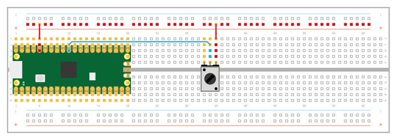
Pick up your potentiometer and turn it over: you’ll see it has three pins which fit in the breadboard. Depending on how you connect these pins, the potentiometer responds in two different ways. Unplug your Pico from USB, then insert the potentiometer into your breadboard, being careful not to bend the pins. Wire the middle pin to pin GP26_ADC0 on your Pico using a male-to-male (M2M) jumper wire (see Figure 8-1) If your breadboard is oriented as shown, it’ll be above the Pico in column ten. Finally, take two more jumper wires and wire either of the potentiometer’s outer pins to your breadboard’s power rail and the power rail to your Pico’s 3V3 pin.
Open ViperIDE and begin a new program:
import machine
import time
Like the digital general-purpose input/output (GPIO) pins, the analogue input pins are handled by the machine library — and just like the digital pins, they need to be set up before you can use them. Continue your program:
potentiometer = machine.ADC(26)
This configures pin GP26_ADC0 as the first channel, ADC0, on the analogue-to-digital converter. To read from the pin, set up a loop:
while True:
    print(potentiometer.read_u16())
    time.sleep(2)
In this loop, reading the value of the pin and printing it take place on a single line: this is a more compact alternative to reading the value into a variable and then printing the variable, but only works if you don’t want to do anything with the reading other than print it — which is exactly what this program needs at the moment.
Reading an analogue input is just like reading a digital input, except for one thing: when you read a digital input you use read(), but you’re reading this analogue input with read_u16(). That last part, u16, simply warns you that rather than receiving a binary 0 or 1 result, you’ll receive an unsigned 16-bit integer — a whole number between 0 and 65,535.
Connect your Pico to your computer or Raspberry Pi over USB, then save your program as Potentiometer.py and click the Run icon. Watch the Terminal: you’ll see your program print out a large number, likely over 60,000. Try turning the potentiometer all the way in one direction: depending on the direction you turned the knob and which outer leg you connected, the number will go up or down. Turn it the other way: the value will change in the opposite direction.
No matter which way you turn it, though, it will never get anywhere near 0. That’s because with only two legs connected, the potentiometer is acting as a component known as a variable resistor or varistor. A varistor is a resistor with a value you can change — in the case of a 10 kΩ potentiometer, between 0 Ω and 10,000 Ω. The higher the resistance, the less voltage from the 3V3 pin reaches your analogue input — so the number goes down. The lower the resistance, the more voltage reaches your analogue input — so the number goes up.
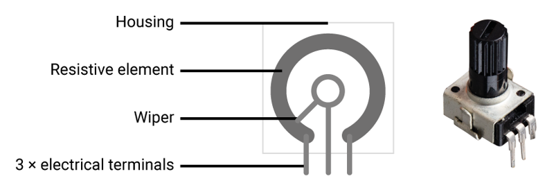
A potentiometer works by having a conductive strip inside, connected to the two outer pins, and a wiper or brush connected to the inner pin (Figure 8-2). As you turn the knob, the wiper moves closer to one end of the strip and further away from the other. The further the wiper gets from the end of the strip you wired to your Pico’s 3V3 pin, the higher the resistance; the closer it gets, the lower the resistance.
Varistors are extremely useful components, but there’s a drawback: you’ll notice no matter how far you turn the knob in either direction, you can never get a value of 0 — or anywhere close to it. That’s because a 10 kΩ resistor isn’t strong enough to drop the 3V3 pin’s output to 0V. You could look for a bigger potentiometer with a higher maximum resistance, or you could simply wire your existing potentiometer up as a voltage divider.
A potentiometer as a voltage divider
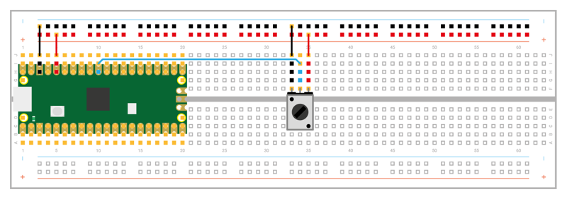
The unused pin on your potentiometer isn’t there for show: adding a connection to that pin to your circuit completely changes how the potentiometer works. Stop your program, disconnect your Pico from USB, and grab two male-to-male (M2M) jumper wires. Use one to connect the unused pin of your potentiometer to your breadboard’s ground rail as shown in Figure 8-3. Take the other and connect the ground rail to a GND pin on the Pico, such as the one in column 3.
Connect your Pico to USB again, then click the Run icon to restart your program. Turn the potentiometer knob again, all the way one direction then all the way the other. Watch the values that are printed to the Terminal: unlike before, they’re now going from near-zero to nearly a full 65,535 — but why?
Adding the ground connection to the other end of the potentiometer’s conductive strip has created a voltage divider: previously, the potentiometer was simply acting as a resistor between the 3V3 pin and the analogue input pin, it’s now dividing the voltage between the 3.3V output from the 3V3 pin and the 0V of the GND pin. Turn the knob fully one direction, you’ll get 100 percent of the 3.3V; turn it fully the other way, 0 percent.
The number you see printed to the Terminal is a decimal representation of the raw output of the analogue-to-digital converter — but it’s not the friendliest way to see it, especially if you forget that 65,535 means ‘full voltage’.
There’s an easy way to fix that, though: a simple mathematical equation. Go back to your program, and add the following above your loop:
conversion_factor = 3.3 / (65535)
This sets up a mathematical way to convert the number that the analogue-to-digital converter gives you into a fair approximation of the actual voltage it represents. The first number is the maximum possible voltage that the pin can expect: 3.3V, from your Pico’s 3V3 pin; the second number is the maximum value the analogue input reading can be, 65,535.
Taken all together, the conversion factor is a number created by ‘3.3 divided by 65,535’ — the maximum possible voltage divided by the range of values the analogue-to-digital converter reports, which is in turn a feature of its resolution in bits.
With your conversion factor set up, you simply need to use it in your program. Go back to your loop, and edit it to read:
while True:
    voltage = potentiometer.read_u16() * conversion_factor
    print(voltage)
    time.sleep(2)
The first line inside the loop takes a reading from the potentiometer via the analogue input pin, and multiplies it — the * symbol — by the conversion factor you set up earlier in the program, storing the result as the variable voltage. That variable is then printed to the Terminal, in place of the raw reading you used earlier.
Your finished program will look like this:
import machine
import time

potentiometer = machine.ADC(26)
conversion_factor = 3.3 / (65535)

while True:
    voltage = potentiometer.read_u16() * conversion_factor
    print(voltage)
    time.sleep(2)
Click the Run icon. Turn the potentiometer all the way in one direction, then the other. Watch the numbers being printed to the Terminal: you’ll see that when the potentiometer is all the way one way, the numbers get very close to zero; when it’s all the way the other way, they get very close to 3.3. These numbers represent the actual voltage being read by the pin — and as you turn the knob of the potentiometer, you’re dividing the voltage smoothly between minimum and maximum, 0V to 3.3V.
Congratulations: you now know how to wire a potentiometer as both a varistor and a voltage divider, and how to read analogue inputs as both a raw value and a voltage!
Measuring temperatures
Your Raspberry Pi Pico’s RP2040 microcontroller has an internal temperature sensor, which is read on the fourth analogue-to-digital converter channel. Like the potentiometer, the output of the sensor is a variable voltage: as the temperature changes, so does the voltage.
Start a new program, and import the machine and time libraries:
import machine
import time
Set up the analogue-to-digital converter again, but rather than a pin number, you’ll use the ADC channel number for the internal temperature sensor; specify this with the machine.ADC.CORE_TEMP constant:
sensor_temp = machine.ADC(machine.ADC.CORE_TEMP)
You’ll need your conversion factor again, to change the raw reading from the sensor into a voltage value, so add that:
conversion_factor = 3.3 / (65535)
Then set up a loop to take readings from the analogue input, apply the conversion factor, and store them in a variable:
while True:
    reading = sensor_temp.read_u16() * conversion_factor
Rather than print the reading directly, though, you need to do a second conversion — to take the voltage reported by the analogue-to-digital converter and convert it into degrees Celsius:
temperature = 27 - (reading - 0.706)/0.001721
This is another mathematical equation, and one which is specific to the temperature sensor in the microcontroller. The values are taken from a technical document called a data sheet or data book: all electronic components have a data sheet, which is normally available on request from the manufacturer. You can view RP2040 and RP2350 data sheets in the microcontroller documentation at rptl.io/microcontroller-docs (click Silicon and scroll down to Documentation). These are packed full of information on how the microcontrollers work, though it’s aimed at engineers, so it is deeply technical.
Finally, finish your loop:
    print(temperature)
    time.sleep(2)
Your program will now look like this:
import machine
import time

sensor_temp = machine.ADC(machine.ADC.CORE_TEMP)
conversion_factor = 3.3 / (65535)

while True:
    reading = sensor_temp.read_u16() * conversion_factor
    temperature = 27 - (reading - 0.706)/0.001721
    print(temperature)
    time.sleep(2)
save your program as Temperature.py and click the Run icon. Watch the Terminal: you’ll see numbers being printed which represent the temperature reported by the sensor in degrees Celsius.
Try gently pressing the tip of your finger to the microcontroller, the largest black chip in the middle of your Pico, and holding it there: the warmth of your finger should make the chip warmer, and the temperature will rise. Remove your finger from the chip, and the temperature will fall again.
Congratulations — you’ve turned your Pico into a thermometer!
Fading an LED with PWM
The analogue-to-digital converter in your Pico only works one way: it takes an analogue signal and converts it to a digital signal the microcontroller can understand. If you want to go the other way, and have your digital microcontroller create an analogue output, you’d normally need a digital-to-analogue converter (DAC) — but there’s a way to ‘fake’ an analogue signal, using a feature called pulse-width modulation or PWM.
A microcontroller’s digital output can only ever be on or off, 0 or 1. Turning a digital output on and off is known as a pulse and by altering how quickly the pin turns on and off you can change, or modulate, the width of these pulses — hence ‘pulse-width modulation’.
Every GPIO pin on your Pico is capable of pulse-width modulation, but the microcontroller’s pulse-width modulation block is made up of multiple slices, each with two outputs. Look at Figure 8-4: you’ll see that each pin has a letter and a number. The number represents the PWM slice connected to that pin; the letter represents which output of the slice is used.
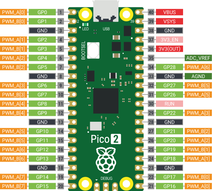
If that sounds confusing, don’t worry: all it means is that you need to make sure you keep track of the PWM slices and outputs you’re using, making sure to only connect to pins with a letter and number combination you haven’t already used. If you’re using PWM_A[0] on pin GP0 and PWM_B[0] on pin GP1, things will work fine, and will continue to work if you add PWM_A[1] on pin GP2; if you try to use the PWM channel on pin GP0 and pin GP16, though, you’d run into problems as they’re both connected to PWM_A[0].
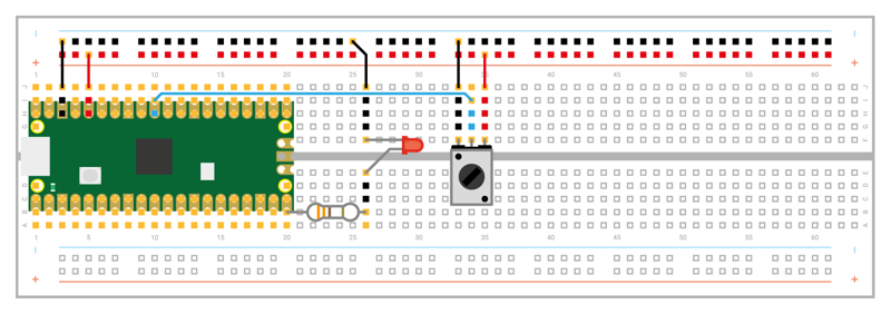
With your Pico disconnected from USB, take an LED of any colour and a 330 Ω current-limiting resistor, and put them in the breadboard as shown in Figure 8-5. Wire the longer leg of the LED, the anode, to pin GP15 via the 330 Ω resistor, and wire the shorter leg to the ground pin of your Pico. Now you can plug your Pico back into USB.
Go back to your first program: open it from your Pico using ViperIDE’s File Manager, loading Potentiometer.py. Delete the line that starts with conversion_factor =, and replace it with this:
led = machine.PWM(machine.Pin(15))
This creates an LED object on pin GP15, but with a difference: it activates the pulse-width modulation output on the pin, channel B[7] — the second output of the eighth slice (slices are counted starting from zero).
You’ll also need to set the frequency, one of the two values you can change to control, or modulate, the pulse width. Add the following line immediately below the previous line:
led.freq(1000)
This sets a frequency of 1000 hertz — one thousand cycles per second. Next, go to the bottom of your program and delete the line starting with voltage = and the print(voltage) line before adding the following. Remember to keep it indented by four spaces so it forms part of the nested code within the loop:
led.duty_u16(potentiometer.read_u16())
Next, replace the 2 in time.sleep(2) with 0.1:
time.sleep(0.1)
This line takes a raw reading from the analogue input connected to your potentiometer, then uses it as the second aspect of pulse-width modulation: the duty cycle. The duty cycle controls the pin’s output: a 0 percent duty cycle leaves the pin switched off for all 1000 pulses per second, and effectively turns the pin off; a 100 percent duty cycle leaves the pin switched on for all 1000 pulses per second, and is functionally equivalent to just turning the pin on as a fixed digital output; a 50 percent duty cycle has the pin on for half the pulses and off for half the pulses.
Click Run and watch the LED as you turn the potentiometer: the LED will grow brighter with the potentiometer turned all the way one way, and gradually dimmer as you turn it the other. That’s because the reading taken from the analogue pin connected to the potentiometer is being turned into a value for the PWM signal’s duty cycle: a low duty cycle is like a low voltage on an analogue output, making the LED dim; a high duty cycle is like a high voltage, making the LED bright.
To make it so you can properly control the LED’s brightness, you need to map the value from the analogue input to a range the PWM slice can understand. The best way to do this is to tell MicroPython that you’re passing the duty cycle value as an unsigned 16-bit integer, the same number format as you receive from your Pico’s analogue input pin. This is why the previous line of code used duty_u16() instead of duty().
Your finished program will look like this:
import machine
import time

potentiometer = machine.ADC(26)
led = machine.PWM(machine.Pin(15))
led.freq(1000)

while True:
    led.duty_u16(potentiometer.read_u16())
    time.sleep(0.1)
Click the Run icon and try turning the potentiometer all the way one way, then all the way the other. Watch the LED: this time, unless you’re using a logarithmic potentiometer, you’ll see the LED’s brightness change smoothly from completely off at one end of the potentiometer knob’s limit to fully lit at the other.
Congratulations: you’ve not only mastered analogue inputs, but you can now create the equivalent to an analogue output using pulse-width modulation!