Lesson 7
Chapter 7: Burglar alarm
Use a motion sensor to detect intruders and sound the alarm with a flashing light and siren
Use a motion sensor to detect intruders and sound the alarm with a flashing light and siren
Another real-world use of microcontrollers is in alarm systems. From the alarm clock that gets you up in the morning to fire alarms, burglar alarms, and even the alarms that sound when there’s a problem at a nuclear power station, microcontrollers help keep us all safe.
In this chapter you’re going to build your own burglar alarm, which works in exactly the same way as a commercial version: a special motion sensor keeps watch for anyone entering the room who shouldn’t be there, and flashes a light while sounding a siren to alert people to the intrusion. Whether you’re protecting a bank vault or trying to keep spying siblings out of your room, or co-workers out of your cubicle, a burglar alarm is sure to come in handy.
For this project you’ll need your Pico-family device; a breadboard; an LED of any colour; a 330 Ω resistor and one or more 8.2 kΩ resistors; an active piezoelectric buzzer; one or more HC-SR501 passive infrared (PIR) sensors; and some male-to-male (M2M) and male-to-female (M2F) jumper wires. You’ll also need a micro USB cable to connect your Pico to a computer.
The HC-SR501 PIR sensor
In previous chapters, you’ve been working with simple input components in the form of push-button switches. This time, you’re going to be using a specialised input known as a passive infrared sensor or PIR. There are hundreds of different PIR sensors available; the HC-SR501 is low-cost, high-performance, and works perfectly with your Pico.
A passive infrared sensor is designed to detect movement — in particular movement from people and other living things. It works a little like a camera, but instead of capturing visible light it looks for the heat emitted from a living body as infrared radiation. It’s known as a passive infrared sensor, rather than active. That’s because, like a camera sensor, it doesn’t send out any signals of its own.
The actual sensor is buried underneath a plastic lens, typically shaped like a half-ball. The lens isn’t technically necessary for the sensor to work, but serves to provide a wider field of vision (FOV); without the lens, the PIR sensor would only be able to see movement in a very narrow angle directly in front of the sensor. The lens serves to pull in infrared from a much wider angle, so a single PIR sensor can watch for movement over most of a room.
In commercial burglar alarm systems, a PIR sensor is only one of the sensors used; others include break-glass sensors which can tell when a window has been smashed, magnetic sensors which monitor whether a door is open or closed, acoustic sensors which can pick up a burglar’s footsteps, and vibration sensors for telling if a lock is being forced open. A simple PIR sensor, though, is often enough for a low-security area — think a reception room, rather than a bank vault.
Pick up your HC-SR501 sensor now and look at it. The first thing to notice is that it has a circuit board of its own, a lot like your Pico — only smaller. As well as the sensor and lens, there are several other components: a small black integrated circuit (IC) which drives the sensor, some capacitors, and tiny surface-mount resistors. You may see one or more small potentiometers which you can twist with a screwdriver to adjust the sensitivity of the sensor and how long it stays active when triggered; leave these as they are for now.
You’ll also see three male pins, exactly like the pins on the bottom of your Pico. You may not be able to push these directly into your breadboard, though, as the components on the board may get in the way. Instead of plugging it into the breadboard, take three male-to-female (M2F) jumper wires and insert the female ends onto the pins on your HC-SR501.
Next, disconnect your Pico from USB. Then, take the male ends and wire them to the breadboard and your Pico. You’ll need to check the documentation for your sensor when wiring it: a lot of different companies make HC-SR501 sensors, and they don’t always use the same pin configuration. For the sensor illustrated in Figure 7-1, the pins are set up so that the ground (GND) pin is on the left, the signal or trigger pin is in the middle, and the power pin is on the right; your sensor may need the wires placed in a different order!
Start with the ground wire: connect it to your breadboard’s ground rail, then connect the ground rail to any of your Pico’s ground pins. In Figure 7-1, it’s connected to Pin 3 on the lower side of the Pico. Next, connect the signal wire; this needs to connect to your Pico’s GPIO pin GP28, along with an external pull-down resistor. Put one leg of an 8.2 kΩ resistor into your breadboard’s ground rail, and the other end into a free hole on the breadboard as shown in Figure 7-1. Connect the PIR signal pin to the same column as the resistor, then connect a jumper wire from that column to GPIO pin GP28 on your Pico. If you have difficulty triggering the sensor with the 8.2 kΩ resistor, try 10 or 20 kΩ.
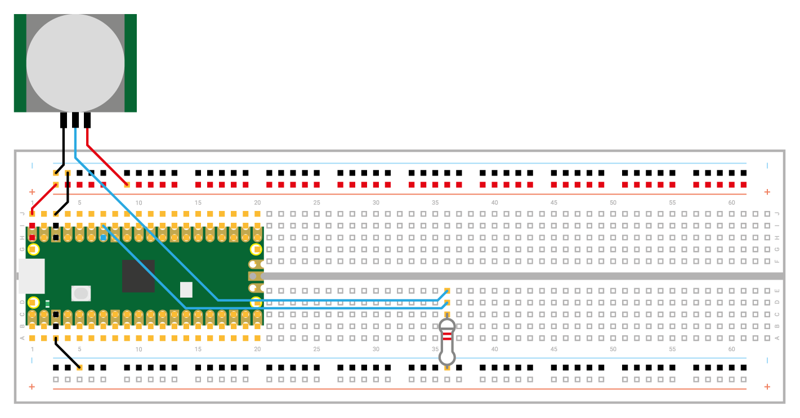
Finally, you need to connect the power wire. Don’t connect the HC-SR501 to your Pico’s 3V3 pin, though: the HC-SR501 is a 5V device, meaning that it needs five volts of electricity to work. If you wire the sensor to your Pico’s 3V3 pin, it won’t work — the pin simply doesn’t provide enough power.
To give your sensor the 5V power it needs, wire it to pin 40 on your Pico — VBUS (if your Pico is oriented as shown in Figure 7-1, it’s the top-left pin). This pin is connected to the micro USB port on your Pico, and taps into the USB 5V power line before it’s converted to 3.3V to run your Pico’s microprocessor. All three HC-SR501 pins should now be wired to your Pico: ground, signal, and power.
If you are using a different PIR, it might operate at a lower voltage. For example, many modules based on the AM312 PIR can be powered at 3.3V, and you could power them from pin 36, 3V3(OUT), instead.
Programming your alarm
You’ll need to program your Pico to recognise the sensor. Handily, this is no more difficult than reading a button — in fact, you can use the very same code. Start by creating a new program and importing the machine library so you can configure your Pico’s GPIO pin, along with the time library which we’ll use to set delays in the program:
import machine
import time
Then set up the pin you wired your HC-SR501 sensor to, GP28:
snsr_pir = machine.Pin(28, machine.Pin.IN)
Like the reaction game you made, a burglar alarm’s inputs should act as an interrupt — stop the program doing whatever it was doing and react whenever the sensor is triggered. As before, start by defining a callback function to handle the interrupt:
def pir_handler(pin):
    time.sleep_ms(100)
    if pin.value():
        print("ALARM! Motion detected!")
Make sure you have correct indentation. The time.sleep_ms(100) and if pin.value(): lines are used to prevent the alarm from being triggered by any jitter in the signal from the PIR sensor: if the pin is no longer active 100 milliseconds after the interrupt is triggered, it was probably a false positive. This process of smoothing out fluctuations is known as debouncing.
Finally, set up the interrupt itself. This isn’t part of the handler function, so delete any spaces that your editor inserts before it:
snsr_pir.irq(trigger=machine.Pin.IRQ_RISING, handler=pir_handler)
That’s enough for now: interrupts stay active regardless of what the rest of the program is doing, so there’s no need to add an infinite loop to keep your program running. Connect the Pico to your Raspberry Pi or computer, then click the Run icon and save the program to your Pico as Burglar_Alarm.py.
Wave your hand slowly over the PIR sensor: a message will print to the Terminal confirming that the sensor saw you. If you keep waving your hand, the message will keep printing — but with a delay between each time it’s printed.
That delay isn’t part of your program, but built into the HC-SR501: the sensor sends a trigger signal to your Pico’s GPIO pin when it detects motion, and keeps the signal on for several seconds before dropping it. On most HC-SR501 sensors, you use a small screwdriver to turn one of its potentiometers to adjust the delay: turn it one way to decrease the delay and the other way to increase it. Check your sensor’s documentation for which potentiometer to use.
Because your interrupt trigger is set to fire on the rising edge of the signal, the message is printed as soon as the PIR sensor sends its signal of 1 or ‘high’ (subject to the debouncing logic, that is). Even if more motion is detected, the interrupt won’t fire again until the built-in delay has passed and the signal has returned to 0, or ‘low’.
Printing a message to the Terminal is enough to prove your sensor is working, but it doesn’t make for much of an alarm. Real burglar alarms have lights and sirens that alert everyone around that something’s wrong — and you can add the same to your own alarm.
Start by wiring an LED, of any colour, to your Pico as shown in Figure 7-2 (disconnect the Pico from USB first). You need to connect the longer leg, the anode, to pin GP15 via a 330 Ω resistor — remember that without this resistor in place to limit the amount of current passing through the LED, you can damage both the LED and your Pico. The shorter leg, the cathode, needs to be wired to one of your Pico’s ground pins — use your breadboard’s ground rail and two male-to-male (M2M) jumper wires for this, wiring the previously unused top ground rail to GPIO Pin 38 as in Figure 7-2.
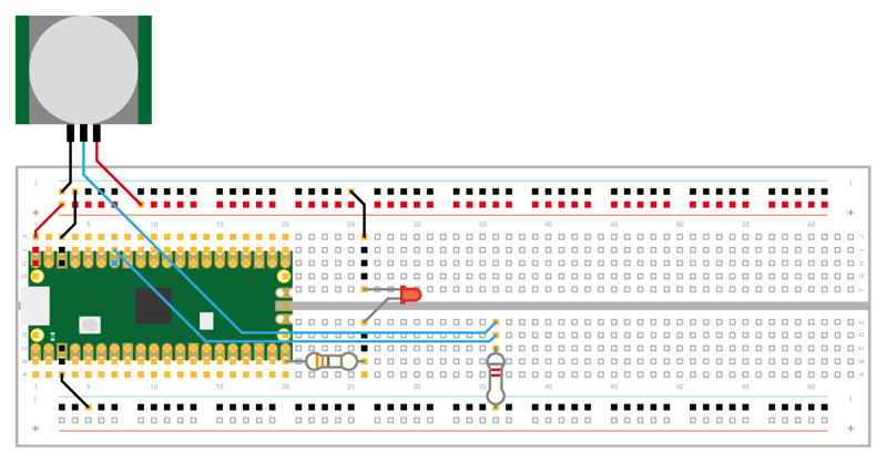
To set up the LED output, add a new line just below where you initialised the PIR sensor’s pin:
led = machine.Pin(15, machine.Pin.OUT)
That’s enough to configure the LED, but you’ll need to make it light up. Add the following new line to your interrupt handler function, under the print line (it should be indented by eight spaces to match that):
for i in range(50):
You’ve just created a finite loop, one which will run 50 times. The letter i represents an increment, a value which goes up each time the loop runs, and which is populated by the instruction range(50).
Give your new loop something to do, remembering that these lines underneath will need to be indented by a further four spaces (twelve in all), as they form both part of the loop you just opened and the interrupt handler function:
led.toggle()
time.sleep_ms(100)
The first of these lines is a feature of the machine library which lets you flip the value of an output pin, rather than set a value — so if the pin is currently 1 (high), toggling it will set it to 0 (low); if the pin is already 0, toggling it will set it to 1.
These two lines of code flash the LED on and off with a 100-millisecond — a tenth of a second — delay. The result is similar to the LED blinking program you wrote back in Chapter 4, Physical computing with Raspberry Pi Pico.
Your program will now look like this:
import machine
import time

snsr_pir = machine.Pin(28, machine.Pin.IN)
led = machine.Pin(15, machine.Pin.OUT)

def pir_handler(pin):
    time.sleep_ms(100)
    if pin.value():
        print("ALARM! Motion detected!")
        for i in range(50):
            led.toggle()
            time.sleep_ms(100)

snsr_pir.irq(trigger=machine.Pin.IRQ_RISING, handler=pir_handler)
Connect the Pico to USB, click the Run icon, then wave your hand over the PIR sensor again: you’ll see the usual alarm message print to the Terminal, then the LED will begin rapidly flashing as a visual alert. Wait for the LED to stop flashing, then wave your hand over the PIR sensor again: the message will print again, and the LED will repeat its flashing pattern.
To make your burglar alarm even more of a deterrent, you can make it flash slowly even when there’s no motion being detected — warning would-be intruders that your room is under observation. Go to the very bottom of your program and add in the following lines:
while True:
    led.toggle()
    time.sleep(5)
Click Run again, but leave the PIR sensor alone: you’ll see the LED is now turning on for five seconds, then turning off for five seconds. This pattern will continue as long as the sensor isn’t triggered; wave your hand over the PIR sensor and you’ll see the LED rapidly flashing again, before going back to its slow-flash pattern. This is because the main program is paused while the interrupt handler runs, so the five-second toggle code you’ve written stops until the handler has finished flashing the LED, then picks up from where it left off.
Inputs and outputs: putting it all together
Your burglar alarm now has a flashing LED to warn intruders away, and a way to see when it’s been triggered without having to watch the Terminal for a message. Now all it needs is a siren — or, at least, a piezoelectric buzzer, which makes sound without deafening your neighbours.
Depending on which model you purchased, your piezoelectric buzzer will have either pins sticking out of the bottom or short wires attached to its sides. If the buzzer has pins, insert these into your breadboard so the buzzer is straddling the centre divide; if it has wires, place these in the breadboard and simply rest the buzzer on the breadboard.
If your buzzer’s wires are long enough, try to connect them to the breadboard columns next to your Pico’s pins; if not, use jumper wires to wire the buzzer as shown in Figure 7-3. Connect the red wire, or the positive pin marked with a + symbol, to pin GP14 at the bottom of your Pico, just to the left of the LED pin. Connect the black wire, or the negative pin marked with a minus (-) symbol (or the letters GND), to the ground rail of your breadboard.
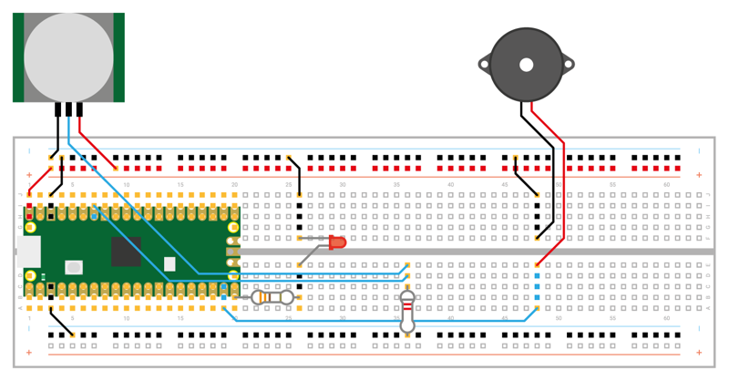
If your buzzer has three pins, connect the leg marked with a minus symbol (-) or the letters GND to the ground rail of your breadboard, the pin marked with S or SIGNAL to pin GP14 on your Pico, and the remaining leg — which is usually the middle leg — to the 3V3 pin on your Pico.
If you run your program now, nothing will change: the buzzer will only make a sound when it receives power from your Pico’s GPIO pins. Go back to the top of your program and initialise the buzzer just below where you initialised the LED:
buzzer = machine.Pin(14, machine.Pin.OUT)
Next, change your interrupt handler to add a new line below led.toggle() — remembering to indent it by twelve spaces to match:
buzzer.toggle()
Your program will now look like this:
import machine
import time

snsr_pir = machine.Pin(28, machine.Pin.IN)
led = machine.Pin(15, machine.Pin.OUT)
buzzer = machine.Pin(14, machine.Pin.OUT)

def pir_handler(pin):
    time.sleep_ms(100)
    if pin.value():
        print("ALARM! Motion detected!")
        for i in range(50):
            led.toggle()
            buzzer.toggle()
            time.sleep_ms(100)

snsr_pir.irq(trigger=machine.Pin.IRQ_RISING, handler=pir_handler)

while True:
    led.toggle()
    time.sleep(5)
Click Run and wave your hand over the PIR sensor: the LED will flash rapidly, as before, but this time it’ll be accompanied by a beeping sound from the buzzer. Congratulations: that should be more than enough to scare an intruder away from ransacking your secret stash of sweets!
If you find your buzzer is clicking, rather than beeping, then you’re using a passive buzzer rather than an active buzzer. An active buzzer has a component inside known as an oscillator, which rapidly moves the metal plate to make the buzzing sound; a passive buzzer lacks this component, meaning you need to replace it with some code of your own.
If you’re using a passive buzzer, try this version of the program instead — it toggles the pin connected to the buzzer on and off very quickly, mimicking the effect of the oscillator in an active buzzer:
import machine
import time

snsr_pir = machine.Pin(28, machine.Pin.IN)
led = machine.Pin(15, machine.Pin.OUT)
buzzer = machine.Pin(14, machine.Pin.OUT)

def pir_handler(pin):
    time.sleep_ms(100)
    if pin.value():
        print("ALARM! Motion detected!")
        for i in range(50):
            led.toggle()
            for j in range(25):
                buzzer.toggle()
                time.sleep_ms(3)

snsr_pir.irq(trigger=machine.Pin.IRQ_RISING, handler=pir_handler)

while True:
    led.toggle()
    time.sleep(5)
Note that the new loop, which controls the buzzer, doesn’t use the letter i to track the increment; that’s because you’re already using that letter for the outer loop — so it uses the letter j. The short delay of just three milliseconds, meanwhile, means the pin connected to the buzzer turns on and off rapidly enough for it to make a buzzing noise.
Try changing the delay to four milliseconds instead of three and you’ll find the buzzer sounds at a lower pitch. Changing the delay changes the buzzer’s oscillation frequency: a longer delay means it oscillates at a lower frequency making it a lower-pitched sound; a shorter delay makes it oscillate at a higher frequency, making it a higher-pitched sound.
Extending your alarm
Burglar alarms rarely cover a single room: instead, they use a network of multiple sensors to monitor multiple rooms from a single alarm system. Your Pico-based burglar alarm can work in exactly the same way, adding in multiple sensors to cover multiple areas at once.
You’ll need a PIR sensor and 8.2 kΩ resistor for each area you want to cover; in this example you’ll add one more sensor for a total of two, but you can keep going and add as many sensors as you need.
Both of your sensors need 5V power to work, but you’ve already used the VUSB pin on your Pico for the first sensor. If your breadboard has enough room, you could put a male-to-female (M2F) jumper wire next to the one connected to your first sensor and use it for the second; a neater approach, though, is to use the power rail on your breadboard.
Disconnect the first sensor’s power wire from the breadboard end, and insert it into the power rail coloured red or marked with a plus (+) symbol. Take a male-to-male (M2M) jumper wire and connect the same power rail to your Pico’s VBUS pin. Next, take a male-to-female (M2F) jumper wire and connect the power rail to your second PIR sensor’s power input pin. If you’re using a 3.3V sensor, use 3V3(OUT) instead of VBUS.
Finally, wire up the ground pin and signal pin of your second PIR sensor as before — but this time connect the signal pin and resistor to pin GP18 on your Pico, as shown in Figure 7-4. Your circuit now has two sensors, each connected to a separate pin. If you have difficulty triggering the sensor with the 8.2 kΩ resistor, try 10 or 20 kΩ instead.
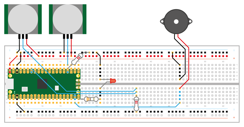
Setting your program up to read the second sensor as well as the first is as simple as adding two new lines. Start by initialising the second sensor, adding a new line below where you initialised the first sensor:
snsr_pir2 = machine.Pin(18, machine.Pin.IN)
Then create a new interrupt, again directly beneath your first interrupt (remember that you can have multiple interrupts with a single handler):
snsr_pir2.irq(trigger=machine.Pin.IRQ_RISING, handler=pir_handler)
Click Run, and wave your hand over the first PIR sensor: you’ll see the alert message, the LED flash, and the buzzer sound as normal. Wait for them to finish, then wave your hand over the second PIR sensor: you’ll see your burglar alarm respond in exactly the same way.
To make your alarm really smart, you can customise the message depending on which pin was responsible for the interrupt — and it works exactly the same way as in the two-player reaction game you wrote earlier. Go back to your interrupt handler and modify it so it looks like:
def pir_handler(pin):
    time.sleep_ms(100)
    if pin.value():
        if pin is snsr_pir:
            print("ALARM! Motion detected in bedroom!")
        elif pin is snsr_pir2:
            print("ALARM! Motion detected in living room!")
        for i in range(50):
            led.toggle()
            buzzer.toggle()
            time.sleep_ms(100)
Just as in the reaction game project in Chapter 6, Reaction game, this code uses the fact that an interrupt reports which triggered it: if the PIR sensor attached to pin GP28 is responsible, it will print one message; if it was the one on GP18, it will print another. Your finished program will look like this:
import machine
import time

snsr_pir = machine.Pin(28, machine.Pin.IN)
snsr_pir2 = machine.Pin(18, machine.Pin.IN)
led = machine.Pin(15, machine.Pin.OUT)
buzzer = machine.Pin(14, machine.Pin.OUT)

def pir_handler(pin):
    time.sleep_ms(100)
    if pin.value():
        if pin is snsr_pir:
            print("ALARM! Motion detected in bedroom!")
        elif pin is snsr_pir2:
            print("ALARM! Motion detected in living room!")
        for i in range(50):
            led.toggle()
            buzzer.toggle()
            time.sleep_ms(100)

snsr_pir.irq(trigger=machine.Pin.IRQ_RISING, handler=pir_handler)
snsr_pir2.irq(trigger=machine.Pin.IRQ_RISING, handler=pir_handler)

while True:
    led.toggle()
    time.sleep(5)
If you’re using a passive, rather than active, buzzer, remember you’ll need to change the buzzer toggle to a loop to have it beep. Click Run and wave your hand over one sensor, then the other, to see both messages print to the Terminal. Congratulations: you now know how to build a modular burglar alarm capable of covering as many areas as you need!