← MicroPython on Raspberry Pi Pico
Lesson 1
Get to know your Raspberry Pi Pico
Get acquainted with your powerful new microcontroller board and learn how to attach pin headers and install MicroPython to program it
Raspberry Pi Pico-family boards are miniature marvels, putting the same technology that underpins everything from smart home systems to industrial factories in the palm of your hand. Whether you’re looking to learn about the MicroPython programming language, take your first steps in physical computing, or want to build a hardware project, Pico — and the amazing community behind it — will support you every step of the way.
Raspberry Pi Pico devices are microcontroller development boards. They’re designed for experimenting with physical computing using a special type of processor: a microcontroller. The size of a stick of gum, the Pico boards pack a surprising amount of power thanks to the chip at their centre: an RP2040 microcontroller for Pico and Pico W, and an RP2350 for Pico 2 and Pico 2 W.
Raspberry Pi Pico boards aren’t designed to replace Raspberry Pi, which is an entirely different class of device known as a single-board computer. You might use Raspberry Pi to play games, write software, or browse the web. Raspberry Pi Pico is designed for physical computing projects, where it is used to control anything from LEDs and buttons to sensors, motors, and even other microcontrollers.
Throughout this book you’ll learn all about the Raspberry Pi Pico boards, but the skills you learn will also apply to any development board based around the RP2040 or RP2350 microcontrollers — and even other devices, so long as they are compatible with the MicroPython programming language.
A guided tour of Raspberry Pi Pico 2
A Raspberry Pi Pico-family microcontroller — ‘Pico’ for short — is a lot smaller than even Raspberry Pi Zero, the most compact of Raspberry Pi’s single-board computers. Despite this, it includes a lot of features — all accessible using the pins around the edge of the board. The second-generation Pico series is available in two versions, Pico 2 and Pico 2 W; you’ll see the difference between the two later. If you have an original Pico or Pico W, the layout of the board is generally the same.
Figure 1-1 shows Raspberry Pi Pico 2 as seen from above. If you look at the longer edges, you’ll see gold-coloured sections with small holes. These are the pins which provide the RP2040 microcontroller with connections to the outside world — known as input/output (IO).
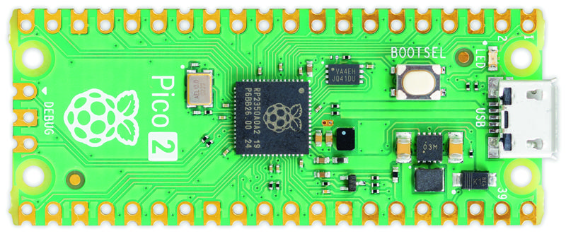
The pins on your Pico 2 are very similar to the pins that make up the general-purpose input/output (GPIO) header on a Raspberry Pi — but while most Raspberry Pi single-board computers come with the physical metal pins already attached, Pico boards do not.
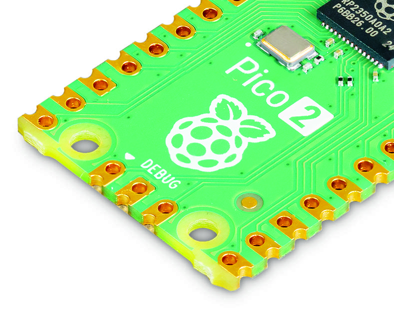
If you want to buy a Pico 2 with headers mounted, look for Raspberry Pi Pico 2 or Pico 2 W with headers. There’s a good reason to offer models without headers attached: look at the outer edge of the circuit board and you’ll see it’s bumpy, with little circular cut-outs (Figure 1-2).
These bumps create what is called a castellated circuit board, which can be soldered on top of other circuit boards without using any physical metal pins. It’s very helpful in builds where you need to keep the height to a minimum, making for a smaller finished project. If you buy an off-the-shelf gadget powered by a Pico-family microcontroller, it’ll almost certainly be fitted using the castellations.
The holes just inwards from the bumps are to accommodate 2.54mm male pin headers. You’ll recognise them as the same type of pins used on the bigger Raspberry Pi’s GPIO header. By soldering these in place pointing downwards, you can push your Pico into a solderless breadboard to make it easy to connect and disconnect new hardware — great for experiments and rapid prototyping!
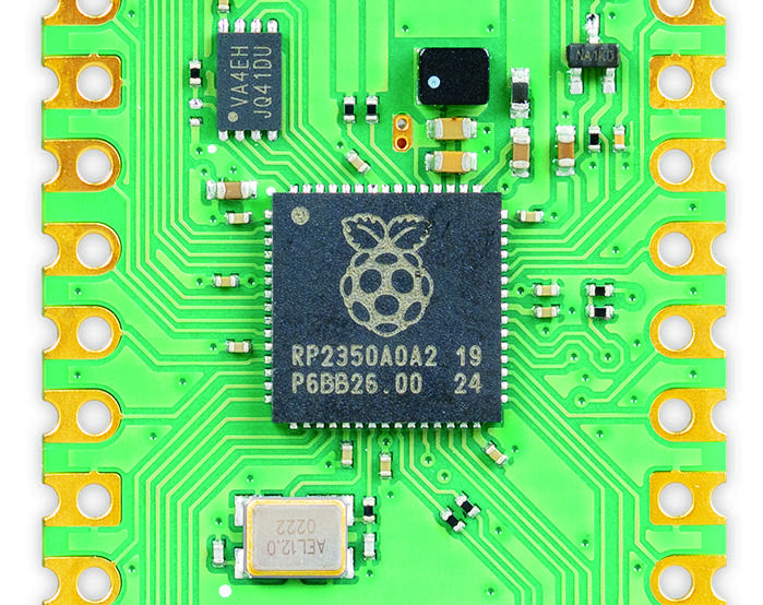
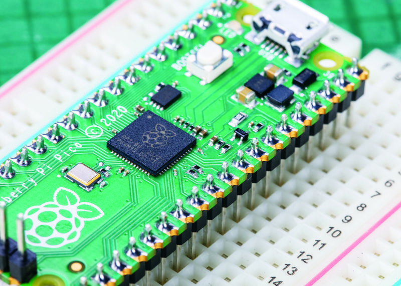
The chip at the centre of your Pico 2 (Figure 1-3) is an RP2350 microcontroller. This is a custom integrated circuit (IC), designed and built by Raspberry Pi to operate as the brains of your Pico and other microcontroller-based devices. If you look at it closely, you’ll see a Raspberry Pi logo etched into the top of the chip along with a series of letters and numbers which let engineers track when and where the chip was made.
At the top of your Pico is a micro USB port (Figure 1-4). This provides power to make your Pico run, and also sends and receives data that lets your Pico talk to a Raspberry Pi or another computer via its USB port. This is how you’ll load programs onto your Pico.
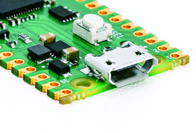
If you hold your Pico up and look at the micro USB port head-on, you’ll see it’s shaped so it’s narrower at the bottom and wider at the top. Take a micro USB cable, and you’ll see its connector is the same.
The micro USB cable will only go into the micro USB port on your Pico one way up. When you’re connecting it, make sure to line the narrow and wide sides up the right way around — you could damage your Pico if you try to brute-force the micro USB cable in the wrong way up!
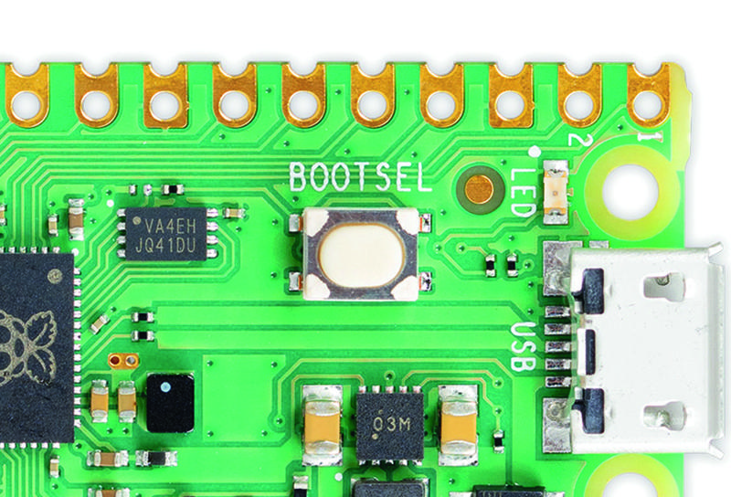
Just below the micro USB port is a small button marked ‘BOOTSEL’, shown in Figure 1-5. ‘BOOTSEL’ is short for boot selection, which switches your Pico between two start-up modes when it’s first switched on. You’ll use the boot selection button later, as you get your Pico ready for programming.
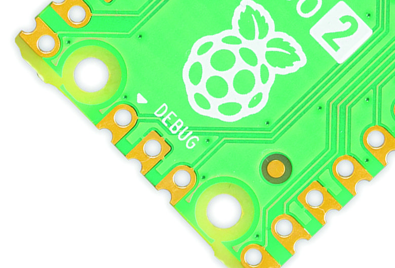
At the bottom of your Pico are three smaller gold pads with the word ‘DEBUG’ above them (Figure 1-6). These are designed for debugging, or finding errors, in programs running on the Pico, using a special tool called a debugger. You won’t need to use the debug header at first, but you may find it useful as you write larger and more complicated programs. On some Raspberry Pi Pico models, the debug pads are replaced by a small, three-pin connector.
Turn your Pico over and you’ll see the underside has writing on it (Figure 1-7). This printed text is known as a silk-screen layer, and labels each of the pins with its core function. You’ll see things like ‘GP0’ and ‘GP1’, ‘GND’, ‘RUN’, and ‘3V3’. If you ever forget which pin is which, these labels will tell you — but you won’t be able to see them when the Pico is pushed into a breadboard, so we’ve printed full pinout diagrams in this book for easier reference.
You might have noticed that not all the labels line up with their pins. The small holes at the top and bottom of the board are mounting holes, designed to allow you to fix your Pico to projects more permanently, using screws or nuts and bolts. Where the holes get in the way of the labelling, the labels are pushed further up or down the board: looking at the top-right. So ‘VBUS’ is the first pin on the left, ‘VSYS’ the second, and ‘GND’ the third.
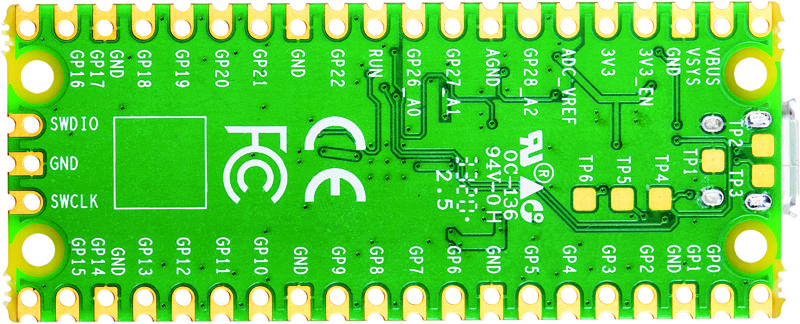
You’ll also see some flat, gold pads labelled with ‘TP’ and a number. These are test points, and are designed for engineers to quickly check that a Raspberry Pi Pico is working after it has been assembled at the factory — you won’t be using them yourself. Depending on the test pad, the engineer might use a multimeter or an oscilloscope to check that your Pico is working properly before it’s packaged up and shipped to you.
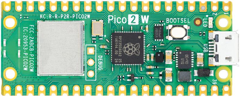
If you have a Raspberry Pi Pico 2 W, you’ll find another piece of hardware on the board: a silver metal rectangle (Figure 1-8). This is a shield for a wireless module, like the one on Raspberry Pi 4 and Raspberry Pi 5, which can be used to connect your Pico to a Wi-Fi network or to Bluetooth devices. It’s connected to a small antenna which sits at the very bottom of the board — which is why you’ll find the debug pads or connector closer to the middle of the board on Raspberry Pi Pico 2 W.
Soldering the headers
Look at a standard Raspberry Pi Pico-family board, and you’ll see it is completely flat. There are no metal pins like you’d find on the GPIO header of your Raspberry Pi or on the Pico-family boards with headers.
The easiest way to use a Pico is to attach it to a solderless breadboard —for that, you’ll need to attach pin headers. You’ll need a soldering iron with a stand, some solder, a cleaning sponge, your Pico, and two 20-pin 2.54 mm male header strips. You can use a solderless breadboard to make the process easier.
Although this section shows how to solder headers to an original Raspberry Pi Pico, the process is the same for a Pico 2.
Sometimes 2.54 mm headers are provided in strips longer than 20 pins. If yours are longer, just count 20 pins in from one end and look at the plastic between the 20th and 21st pins: you’ll see it has a small indentation at either side. This is a break point: if you have flush cutters, you can snip them easily. If not, put your thumbnails in the indentation with the headers in both your left and right hands and bend the strip. It will break cleanly, leaving you with a strip of exactly 20 pins. If the remaining header strip is longer than 20 pins, do the same again so you have two 20-pin strips.
Turn your Pico upside-down, so you can see the silk-screen pin numbers and test points on the bottom. Take one of the two header strips and push it gently into the pin holes on the left-hand side of your Pico. Make sure that it’s properly inserted in the holes, and not just resting in the castellations, and that all 20 pins are in place, then take the other header and insert it into the right-hand side. When you’ve finished, the plastic blocks on the pins should be pushed up against your Pico’s circuit board.
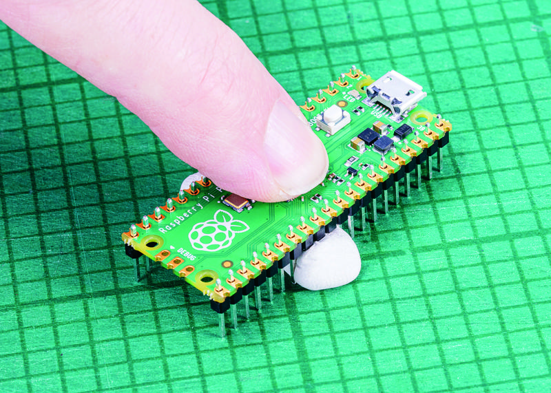
Pinch your Pico at the sides to hold both the circuit board and the two header strips. Don’t let go, or the headers will fall out! If you don’t have a breadboard yet, you’ll need a way to hold the headers in place while you’re soldering — and don’t use your fingers, or you’ll burn them. You can hold the headers in place with small alligator clips, or a small blob of Blu Tack or other sticky putty (Figure 1-9). Solder one pin, then check the alignment: if the pins are at an angle, melt the solder as you carefully adjust them to get everything lined up.
If you do have a breadboard, simply turn your breadboard and Pico upside down — remembering to keep the headers pinched — and use your Pico to gently push the headers into the holes on your breadboard, taking care to make sure the headers aren’t going in at an angle. Keep pushing until your Pico is lying flat, with the plastic blocks on the pin headers sandwiched between your Pico and your breadboard (Figure 1-10).
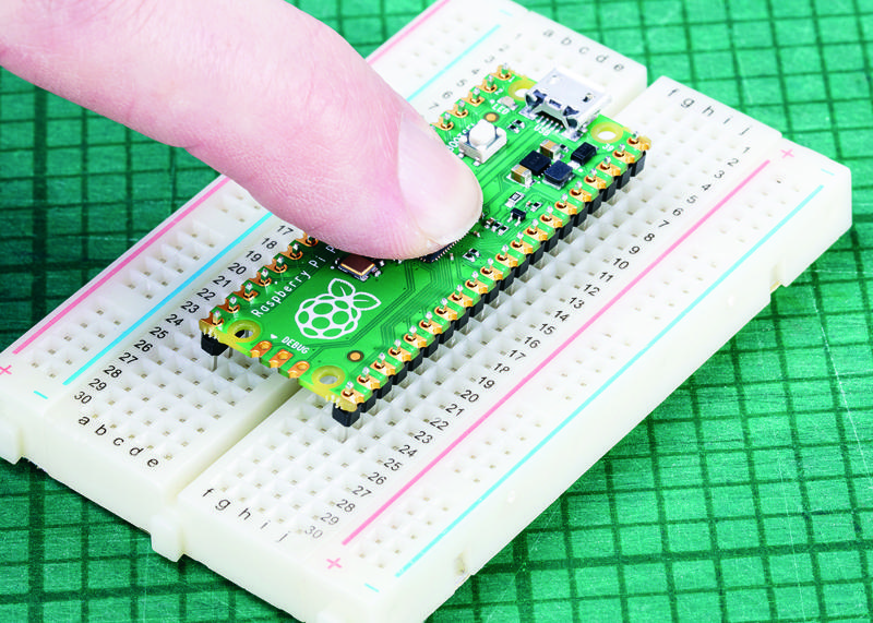
Look at the top of your Pico: you’ll see a small length of each pin is sticking up out of the pin holes. This is the part you’re going to solder — which means heating up both the pins and the pads on the Pico and melting a small amount of a special metal (solder) onto them.
Put your soldering iron in its stand, making sure the metal tip isn’t resting up against anything, and plug it in. It will take a few minutes for the tip of the iron to get hot; while you’re waiting, unroll a small length of solder — about twice as long as your index finger. You should be able to break the solder by pulling and twisting it; it’s a very soft metal.
If your soldering stand has a cleaning sponge, take the sponge to the sink and put a little bit of cold water (preferably distilled or deionized) on it so it softens. Squeeze the excess water out of the sponge, so it’s damp but not dripping, and put it back on the stand. If you’re using a cleaner made of coiled brass wire, you don’t need any water.
Pick up your soldering iron by the handle, making sure to keep the cable from catching on anything as you move it around. Hold it like a pencil, but make sure your fingers only ever touch the plastic or rubber handle area: the metal parts, even the shaft ahead of the actual iron tip, will be extremely hot and can burn you very quickly.
Before you begin soldering, clean the iron’s tip: brush it along your sponge or coiled wire cleaner. Take your length of solder, holding it at one end, and push the other end onto the tip of your iron: it should quickly melt into a blob. If it doesn’t, leave your soldering iron to heat up for longer — or try giving the tip another clean.
Putting a blob of solder on the tip is known as tinning the iron. The flux in the solder helps to burn off any oxidation still on the tip of the iron, and gets it ready. Wipe the iron on your sponge or cleaning wire again to clean off the excess solder; the tip should be left looking shiny and clean.
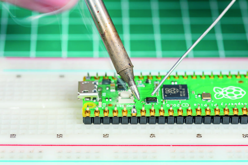
Put the iron back in the stand, where it should always be unless you’re actively using it, and move your Pico so it’s in front of you. Pick up the iron in one hand and the solder in the other. Press the tip of the iron against the pin closest to you, so that it’s touching both the vertical metal pin and the gold-coloured pad on your Pico at the same time (Figure 1-11).
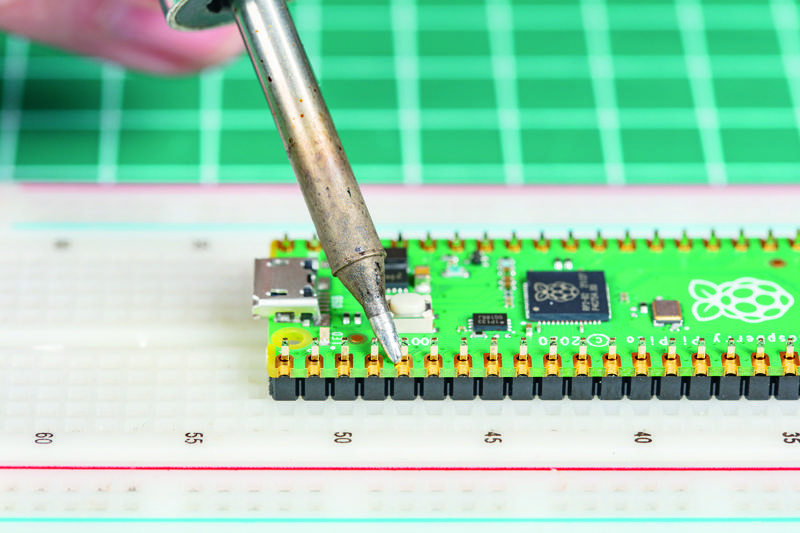
It’s important that the pin and the pad are both heated up, so keep your iron pressed against both while you count to three. When you’ve reached three, still keeping the iron in place, press the end of your length of solder gently against both the pin and pad but on the opposite side to your iron tip, as shown in Figure 1-12. Just like when you tinned the tip, the solder should melt quickly and begin to flow.
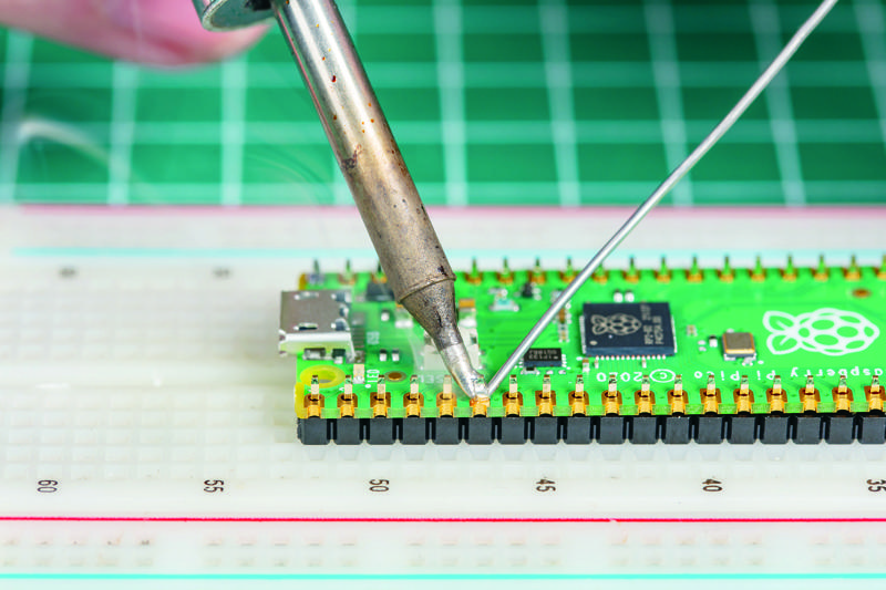
The solder will flow around the pin and the pad, but no further: that’s because your Pico’s circuit board is coated in a layer called solder resist which keeps the solder where it needs to be. Make sure not to use too much solder: a little goes a long way.
If you’re using Blu Tack or some other putty, solder the corner pins first to anchor the headers, then remove the putty before you solder any more. That way, you don’t have to worry about melting the putty as you solder.
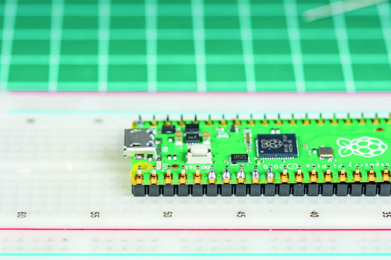
Pull the remaining part of your solder away from the joint, making sure to keep the iron in place. If you pull the iron away first, the solder will harden and you won’t be able to remove the piece in your hand; if that happens, just put the iron back in place to melt it again. Once the molten solder has spread around the pin and pad (Figure 1-13), which should only take a second or so, remove the soldering iron. Congratulations: you’ve soldered your first pin!
Clean the tip of your iron on your sponge or brass wire, and put it back in the stand. Pick up your Pico and look at your solder joint: it should fill the pad and rise up to meet the pin smoothly, looking a little like a volcano shape with the pin filling in the hole where the lava would be, as shown in Figure 1-14.
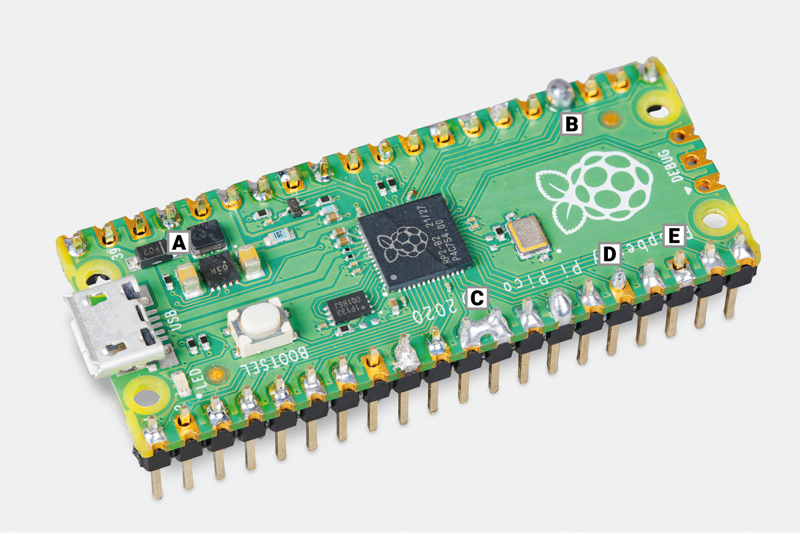
If the solder is too hot, it won’t flow well and you’ll get an overheated joint with some burnt flux (example A in Figure 1-15). This can be removed with a bit of careful scraping with the tip of a knife, or a toothbrush and a little 90% isopropyl alcohol.
On the other hand, if the solder is entirely covering the pin, as in example B in Figure 1-15, you used too much. That’s not necessarily going to cause a problem, though it doesn’t look very attractive: so long as none of the solder is touching any of the pins around it, it should still work. If it is touching other pins (as in example C of Figure 1-15), you’ve created a bridge which will cause a short circuit.
Again, bridges are easy to fix. First, try reflowing the solder on the joint you were making; if that doesn’t work, put your iron against the pin and pad at the other side of the bridge to flow some of it into the joint there. If there’s still far too much solder, you’ll need to remove the excess before you use your Pico: you can buy desoldering braid, which you press against the molten solder to wick the excess up, or a desoldering pump to physically suck the molten solder up.
If the solder is sticking to the pin but not sticking to the copper pad, as in example D in Figure 1-15, then the pad wasn’t heated up enough. Don’t worry, it’s easily fixed: take your soldering iron and place it where the pad and pin meet, making sure that it’s pressing against both this time. After a few seconds, the solder should reflow and make a good joint.
Another common mistake is too little solder: if you can still see copper pad, or there’s a gap between the pin and the pad which isn’t filled in with solder, you used too little (example E in Figure 1-15). Put the iron back on the pin and pad, count to three, and add a little more solder. Too little is always easier to fix than too much, so remember to take it easy with the solder!
Once you’re happy with the first pin, repeat the process for all 40 pins on your Pico — leaving the three-pin ‘DEBUG’ header at the bottom empty. Tip: solder the four corner pins first. Take your time, don’t rush, and remember that mistakes can always be fixed. Remember to clean your iron’s tip regularly during your soldering, and if you find things are getting difficult, melt some solder on it to re-tin the tip. Be sure to keep refreshing your length of solder, too: if it’s too short and your fingers are too close to the iron’s tip, you can burn yourself.
When you’re finished, and you’ve checked all the pins for good solder joints and to make sure they’re not bridged to any nearby pins, clean and tin the iron’s tip one last time before putting it back in the stand and unplugging it. Make sure to let the iron cool before you put it away: soldering irons can stay hot enough to burn you for a long time after they’ve been unplugged!
Finally, it’s time to wash your hands — and celebrate your new skill as a soldering supremo!
Installing MicroPython
Now that your Pico is ready to go (Figure 1-16), there’s only one thing left to do to get it ready: install MicroPython onto it. Start by plugging a micro USB cable into the micro USB port on your Pico — make sure it’s the right way up before gently pushing it in the rest of the way.
Hold down the ‘BOOTSEL’ button on the top of your Pico. Then, while still holding it down, connect the other end of the micro USB cable to one of the USB ports on your computer. Count to three, then let go of the button.
After a few more seconds you should see your Pico appear as a removable drive, as though you’d connected a USB flash drive or external hard drive.
On a Raspberry Pi, you’ll see a pop-up asking if you’d like to open the drive in the File Manager. Make sure Open in File Manager is selected and click OK.
On Windows, you may see an autoplay notification. You can click that and then choose Open Folder to View Files. Alternatively, you can open File Explorer, navigate to This PC, and double-click the RPI-RP2 (Pico 1 series) or RP2350 (Pico 2 series) drive to open it.
On an Apple Mac, it’s likely to quietly mount the drive without fanfare. Open the Finder and look for RPI-RP2 or RP2350 in the sidebar to the left of the Finder window. It’s likely to appear under Locations. If the sidebar is not visible, click View and select Show Sidebar.
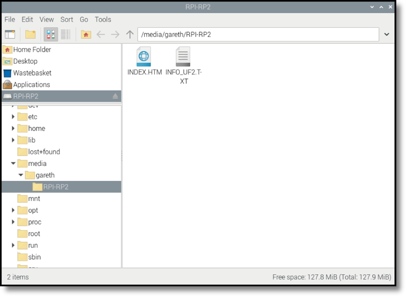
In the File Manager window, you’ll see two files on your Pico (Figure 1-17): INDEX.HTM and INFO_UF2.TXT. The second file contains information about your Pico, such as the version of the bootloader it’s currently running. The first file, INDEX.HTM, is a link to the Raspberry Pi Pico website. Double-click on this file or open your web browser and type rptl.io/microcontroller-docs into the address bar.
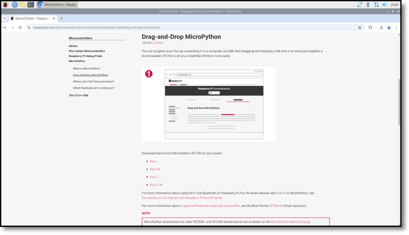
When the web page opens, you’ll see information about Raspberry Pi’s Pico-family boards. Click on the MicroPython box to go to the firmware download page. Scroll down to the section labelled Drag-and-Drop MicroPython, as shown in Figure 1-18, and find the link for the version of MicroPython for your board. There’s one for Raspberry Pi Pico and Pico H, another for Raspberry Pi Pico W and Pico WH, a third for Raspberry Pi Pico 2 and Pico 2 H, and a fourth for Raspberry Pi Pico 2 W and Pico 2 WH. Click on the link to download the appropriate UF2 file. If you accidentally download the wrong file, don’t worry; you can come back to the page at any time and flash new firmware onto your device using the same process.
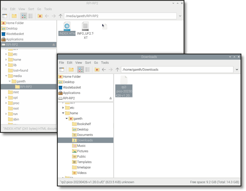
Open a new File Manager (Raspberry Pi), Windows Explorer, or macOS Finder window, then navigate to your Downloads folder and find the file you just downloaded. it will be called rp2-pico, rp2-pico-w, RPI_PICO2, or RPI_PICO2W followed by a date, some identifying text and numbers, along with the extension uf2.
Click and hold the mouse button on the UF2 file, then drag it to the other window that’s open on your Pico’s removable storage drive. Hover it over that window and let go of the mouse button to drop the file onto your Pico, as shown in Figure 1-19.
After a few seconds you’ll see your Pico drive window disappear from File Manager, Explorer, or Finder, and you may also see a warning that a drive was removed without being ejected. Don’t worry, that’s supposed to happen! When you dragged the MicroPython firmware file onto your Pico, you told it to flash the firmware onto its internal storage. To do that, your Pico switches out of the special mode you put it in with the ‘BOOTSEL’ button, flashes the new firmware, and then loads it — your Pico is now running MicroPython.
Congratulations: you’re now ready to get started with MicroPython on your Raspberry Pi Pico!