Lesson 10
Chapter 10: Digital communication protocols: I2C and SPI
Explore these two popular communication protocols and use them to display data on an OLED display
Explore these two popular communication protocols and use them to display data on an OLED display
So far we’ve looked at how to work with a few common bits of hardware, but as you build more projects on your own, you’ll probably want to branch out to use all sorts of different sensors, actuators, and displays. How will you communicate with these? Even if there’s a MicroPython library you can use that converts the low-level functions into an easy-to-use package, some of the low-level interfaces require a bit more thought to work with.
There are a couple of standard low-level interfaces for connecting digital devices available in MicroPython: Inter-Integrated Circuit (I2C) and Serial Peripheral Interface (SPI). In many ways, they’re very similar in that they both define a way of establishing a two-way interface between two devices. In fact, many components are available in both SPI and I2C versions, so you can pick the one that’s right for your project. With either protocol, there’s one device that controls the communication (your Pico-family board) and one (or more) that waits for instructions from the main device. However, there are a few differences, which you’ll learn about as you use them.
I2C
Communication over I2C takes place on two wires: a clock (marked as SCL or SCK) and a data channel (usually marked SDA).
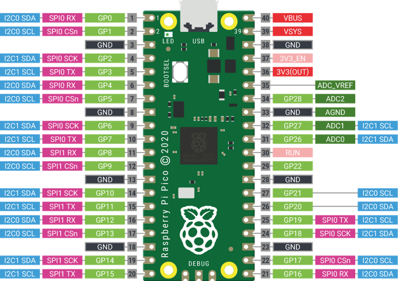
I2C will only work with certain pins on the Pico. There are a few choices; look at the pinout diagram for the options (Figure 10-1). There are two I2C buses (I2C0 and I2C1), and you can use either or both. In our example, we’ll use I2C0 — with GP0 for SDA, and GP1 for SCL.
To demonstrate the protocols, we’ll use an affordable organic light-emitting diode (OLED) module based on the SSD1306 controller, which are available from a wide variety of suppliers in both I2C and SPI.
You will sometimes find a module that has both interfaces on the same board. you can select which interface to use with either a jumper or a small drop of solder that acts as a bridge across two pads. Remember when we warned you in “Soldering the headers” to avoid bridges? This is one of those rare cases one might be useful!
The first example assumes you’re using a 0.91” 128x32 pixel SSD1306 display. This model typically has four pins: 3.3V (labelled VCC), ground (GND), and two pins for I2C (SDA and SCL). You can display text or graphics on it.
Wiring I2C is just a case of connecting the SDA pin on the Pico with the SDA pin on the OLED and the SCL pin to the OLED’s SCK. Because of the way I2C handles communication, there also needs to be a resistor connecting SDA to 3.3V and SCL to 3.3V. Typically these are about 4.7 kΩ. However, with our device, these resistors are already included, so we don’t need to add any extra ones. Disconnect your Pico from USB while wiring this up, but plug it back in when you’re ready to program.
You’ll need to install a library that isn’t included with MicroPython to work with this module: ssd1306.py, the official MicroPython display driver. Search for “micropython ssd1306.py” to find the official driver file in the micropython-lib repository, and save it to your computer. MicroPython looks for extra libraries in a folder named lib, so if that folder doesn’t already exist on your Pico yet, create it first by typing import os then os.mkdir("lib") into the Terminal. Then use ViperIDE’s File Manager to upload ssd1306.py into that lib folder. You’ll need to do this for each Pico that you want to use with this module.
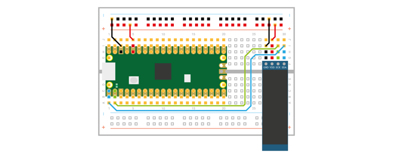
With this wired up (see Figure 10-2), displaying information on the screen is as simple as running this code:
import machine
import ssd1306

sda = machine.Pin(0)
scl = machine.Pin(1)
i2c = machine.I2C(0, sda=sda, scl=scl, freq=400000)
display = ssd1306.SSD1306_I2C(128, 32, i2c)

display.text("Hello, Pico!", 0, 0, 1)
display.show()
This code configures the I2C connection, and creates an object (display) to represent the 128x32 pixel device. Next, it sends some text to the display, and tells the display to show it. The three arguments to the text function are the X and Y position of the text followed by the number of the colour to use. Your SSD1306 module is monochrome, so there’s only two colours you can choose (0 would erase the pixels where the text should appear).
There’s a bit more going on here. Look in ViperIDE’s File Manager, inside the lib folder, for ssd1306.py. Click it to open it in the editor. Scroll down to the line that starts with class SSD1306_I2C and look at the first few lines of the __init__ function:
def __init__(self, width, height, i2c, addr=0x3C,
             external_vcc=False):
    self.i2c = i2c
    self.addr = addr
The 0x3C in the first line refers to the address of the I2C device. You can connect many devices to an I2C bus, and each time you want to send or receive data, you need to specify the address of the device you want to communicate with. The self.addr = addr line stores the address inside the SSD1306_I2C so it can be accessed later.
The write_cmd function is used inside the library to send commands to the module. Note how it specifies the address as the first argument to i2c.writeto:
def write_cmd(self, cmd):
    self.temp[0] = 0x80  # Co=1, D/C#=0
    self.temp[1] = cmd
    self.i2c.writeto(self.addr, self.temp)
This address is hard-wired into the device (though you may be able to change it on some devices by cutting a trace on the PCB, or soldering a blob — see your device’s documentation for details).
You should find the address for any device in its documentation, but you can scan an I2C bus to see what addresses are currently in use. After setting up the I2C bus, you can run the scan method to output the addresses currently in use:
import machine
sda=machine.Pin(0)
scl=machine.Pin(1)
i2c=machine.I2C(0,sda=sda, scl=scl, freq=400000)
print(i2c.scan())
Of course, there’s not much use in a screen that just says Hello World, so let’s turn this into something a little more useful — a thermometer. In Chapter 8, Temperature gauge you learned how to use the ADC to read temperatures using your Pico’s internal temperature sensor. We can now build on this code to make a standalone thermometer that doesn’t need a computer to read the output. With your LCD still connected as before, run the following code:
import machine
import ssd1306
import time

sda = machine.Pin(0)
scl = machine.Pin(1)
i2c = machine.I2C(0, sda=sda, scl=scl, freq=400000)
display = ssd1306.SSD1306_I2C(128, 32, i2c)

adc = machine.ADC(machine.ADC.CORE_TEMP)
conversion_factor = 3.3 / (65535)
while True:
    reading = adc.read_u16() * conversion_factor
    temperature = 27 - (reading - 0.706)/0.001721
    display.fill(0)
    display.text(f"Temp: {temperature}", 0, 0, 1)
    display.show()
    time.sleep(2)
This should mostly look familiar. The only slight change to the previous temperature code is that before we outputted the result of our calculation — a number — but the OLED needs characters to display, so we place the variable between braces ( { and } ) and embed it in an f-string — this converts the number to a string of characters. We make the output slightly more informative by prefixing the value with "Temp: ". Note that we clear the screen with fill(0) so we don’t draw new text over the output of previous readings.
As you’ve seen, I2C is an easy way of linking extra hardware to your Pico. You will need an appropriate library for any device you want to connect, but once you have that, you can easily add all sorts of bits and bobs to your Pico and create impressive builds. You may come across new or exotic hardware that doesn’t yet have a library, but if you do, you can usually determine how to work with it using its documentation and by consulting libraries that others have written for similar devices.
Serial Peripheral Interface
We’ve seen how I2C works, now let’s look at SPI. We’ll use a slightly different SSD1306 module (a 0.96” 128x64 module that supports SPI), so the commands and everything else are mostly the same, it’s just the protocol we send data over that’s different.
SPI has four connections: SCK, MOSI, MISO, and CS (sometimes labelled SS). SCK is the clock, MOSI is the line taking data from your Pico to the module, and MISO takes data from a peripheral device to your Pico. CS (Chip Select) is used to connect many devices to a single SPI bus. You simply take the CS line high to enable an SPI peripheral and pull it low to disable it. In this case of this module, there’s an additional reset line (RES) that the library uses to initialise the SSD1306 chip.
Disconnect your Pico from USB, then wire the display as shown in Figure 10-3. After it’s wired up, reconnect the USB cable so you can program the device. Here’s an overview of the connections you need to make:
| Raspberry Pi Pico Pin | Breadboard Column | SSD1306 Pin |
|---|---|---|
| SCK (GP10 / SPI0 SCK) | 14 | SCK (or CLK) |
| MOSI (GP11 / SPI0 TX) | 15 | SDA (or DIN) |
| MISO (GP12 / SPI0 RX) | 16 | DC |
| CS (GP13 / SPI0 CSn) | 17 | CS |
| GP14 | 19 | RES |
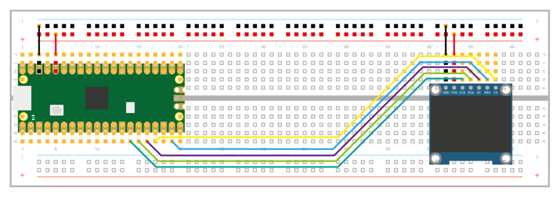
There are no addresses in SPI, so we can just dive in and write our code:
import machine
import ssd1306

mosi = machine.Pin(11)
sck = machine.Pin(10)
res = machine.Pin(14)
dc = machine.Pin(12)
cs = machine.Pin(13)

spi = machine.SPI(1, 100000, mosi=mosi, sck=sck)
display = ssd1306.SSD1306_SPI(128, 64, spi, dc, res, cs)

display.text("Hello World!", 0, 0, 1)
display.show()
In this case, we’re using SPI1, and one set of available pins for this is GP10, GP11, GP12, and GP13. Most types of serial communication have a speed or baudrate, which is basically how many bits of data it can push through the channel per second. A lot of things affect this, such as the capabilities of the two devices being connected and the wiring between them (how long it is and if there’s interference from other devices). If you find you’re having problems with mangled data, then you may need to reduce it. For our little screen, we’re just sending one byte of data per character, so it doesn’t really matter how fast we send it, but for some other SPI devices, fine-tuning the baud rate can be important.
Let’s take a look at how this leaves our thermometer code:
import machine
import ssd1306
import time

mosi = machine.Pin(11)
sck = machine.Pin(10)
res = machine.Pin(14)
dc = machine.Pin(12)
cs = machine.Pin(13)

spi = machine.SPI(1, 100000, mosi=mosi, sck=sck)
display = ssd1306.SSD1306_SPI(128, 64, spi, dc, res, cs)

adc = machine.ADC(machine.ADC.CORE_TEMP)
conversion_factor = 3.3 / (65535)
while True:
    reading = adc.read_u16() * conversion_factor
    temperature = 27 - (reading - 0.706)/0.001721
    display.fill(0)
    display.text(f"Temp: {temperature}", 0, 0, 1)
    display.show()
    time.sleep(2)
As you can see, there’s really very little difference in the code between I2C and SPI. Once you’ve got everything set up, the only really change is that with I2C, you must specify the address when you send data, while with SPI you don’t (though remember if you had more than one device attached, you’d need to toggle the CS GPIO to select the appropriate device).
So, if they’re so similar, which protocol should you choose when building a project? There are a few factors to consider. The first is availability of the things you want to attach. Sometimes a sensor is only available as I2C or SPI, so you have to use that. However, if you’ve got a choice of hardware, the biggest impact comes when you’re using multiple extra devices. With I2C, you can connect as many as 128 devices to a single I2C bus; however, they all need to have a separate address. These addresses are hard-wired in. Sometimes it’s possible to change the address with a solderable (or cuttable) connection, but sometimes it’s not. If you want to have multiple of the same type of sensors (for example, if you’re monitoring the temperature at many points on your project), you may be limited by the number of I2C addresses for your sensor. In this case, SPI may be a better choice.
Alternatively, SPI can have an unlimited number of devices connected; however, each one has to have its own CS line. On the Pico, there are 26 GPIO pins. You need three of them for the SPI bus, so that means there are 23 available for CS lines. And this is assuming you don’t need any for anything else. If available GPIOs are at a premium, consider I2C instead.
In reality, for many projects, you can quite happily use either protocol, and you may find that the choice of which to use has more to do with what parts you find in your parts box than a technical difference between the two.