← MicroPython on Raspberry Pi Pico
Lesson 3
Physical computing
Learn about your Raspberry Pi Pico’s pins and the electronic components you can connect and control
When people think of ‘programming’ or ‘coding’, they’re usually — and naturally — thinking about software. Coding can be about more than just software, though: it can affect the real world through hardware. This is called physical computing. As the name suggests, physical computing is all about controlling things in the real world with your programs: hardware, rather than software. When you set the program on your washing machine, change the temperature on your programmable thermostat, or press a button at traffic lights to cross the road safely, you’re using physical computing.
These devices are typically controlled by a microcontroller very much like the one on your Raspberry Pi Pico-family device — and it’s entirely possible for you to create your own control systems by learning to take advantage of your Pico’s capabilities, just as easily as you learned to write software that runs on your Pico.
Your Pico’s pins
Your Pico talks to hardware through the series of pins along both its edges. Most work as programmable input/output (PIO) pins, meaning they can be programmed to act as either an input or an output, and have no preset purpose of their own until you assign one. Some pins have extra features and alternative modes for communicating with more complicated hardware; others have a specific purpose, providing connections for things like power.
Raspberry Pi Pico’s 40 pins are labelled on the underside of the board, with three also labelled with their numbers on the top of the board: Pin 1, Pin 2, and Pin 39. These top labels help you remember how the numbering works: Pin 1 is at the top-left as you look at the board from above, with the micro USB port to the upper side. Pin 20 is the bottom-left, Pin 21 the bottom-right, and Pin 39 one below the top-right with the unlabelled Pin 40 above it. The labelling on the underside is more thorough, but you won’t be able to see it when your Pico is plugged into a breadboard!
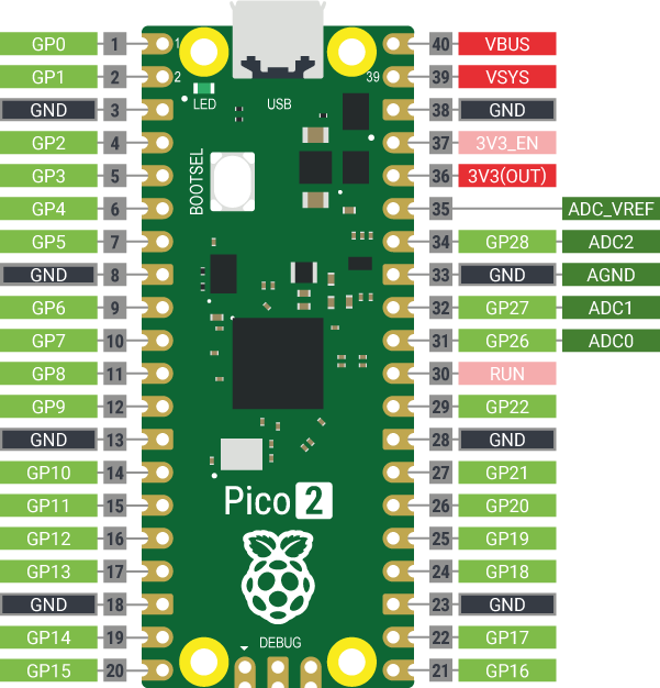
On the Raspberry Pi Pico, pins are usually referred to by their functions (see Figure 3-1) rather than by number. There are several categories of pin types, each of which has a particular function:
- 3V3(OUT) — 3.3 volts power — A source of 3.3V power generated from the VSYS input. This power supply can be switched off by shorting the pin above it (3V3_EN) to GND, which also switches your Pico off.
- VSYS — ~2-5 volts power — A pin directly connected to your Pico’s internal power supply, which cannot be switched off without also switching the Pico off.
- VBUS — 5 volts power — A source of 5V power taken from your Pico’s micro USB port, and used to power hardware which needs more than 3.3V. If you are connection the output of a component to your Pico’s GPIO pins, take care that the component’s output pins do not exceed 3.3V.
- GND — 0 volts ground — A ground connection, used to complete a circuit connected to a power source. Several GND pins are dotted around your Pico to make wiring easier.
- GPxx — General-purpose input/output pin number ‘xx’ — The GPIO pins available for your program, labelled GP0 through to GP28.
- GPxx_ADCx — General-purpose input/output pin number ‘xx’, with analogue input number ‘x’ — A GPIO pin which ends in ADC and a number can be used as an analogue input as well as a digital input or output — but not both at the same time.
- ADC_VREF — Analogue-to-digital converter (ADC) voltage reference — A special input pin which sets a reference voltage for any analogue inputs.
- AGND —ADC 0 volts ground — A special ground connection for use with the ADC_VREF pin.
- RUN — Enables or disables your Pico — The RUN pin is used to start and stop your Pico from another microcontroller or other controlling device.
Several of the GPIO pins have additional functions, which you’ll learn about later in the book. For a full pinout including these additional functions, see Appendix B, Pinout guide.
Electronic components
Your Pico is only part of what you’ll need to work with physical computing. You’ll also need some electrical components, the devices you’ll control from Pico’s GPIO pins. There are thousands of different components available, but most physical computing projects are made using the following common parts.
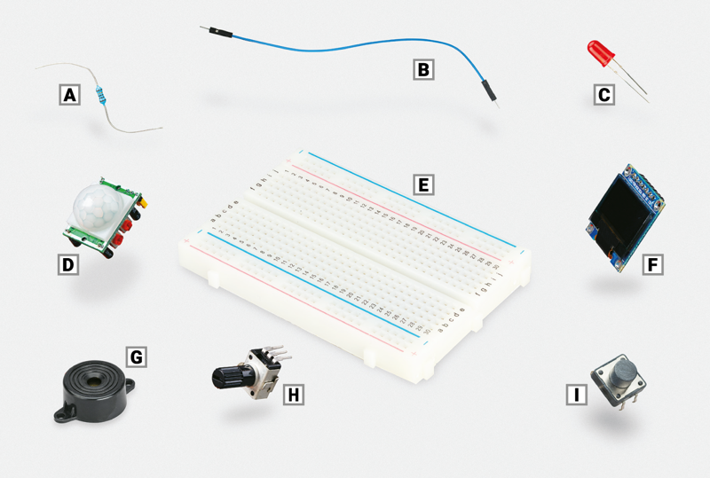
- Resistor (A) — these components control the flow of electrical current and are available in different values, measured using a unit called ohms (Ω). The higher the number of ohms, the more resistance is provided. For Pico physical computing projects, you’ll often use resistors rated at around 330Ω to protect LEDs from drawing too much current and damaging themselves or your Pico. You’ll need higher-value resistors, around 8.2 kΩ, for some projects in this book, but values as high as 20 kΩ are handy. Many suppliers sell packs of assorted values.
- Jumper wires (B) — also known as jumper leads, connect components to your Pico and, if you’re not using a breadboard, to each other. They are available in three versions: male-to-female (M2F); female-to-female (F2F), which can be used to connect individual components to your Pico if you’re not using a breadboard; and male-to-male (M2M), which is used to make connections from one part of a breadboard to another. Depending on your project, you may need all three types of jumper wire. If you’re using a breadboard, you can usually get away with just M2F and M2M jumper wires.
- Light-emitting diode (LED, C) — this is an output device which you can control directly from your program. An LED lights up when it’s powered on, and you’ll find them all over your house: from the small ones which let you know when you’ve left your washing machine switched on, to the large ones you might have lighting up your rooms. LEDs are available in a wide range of shapes, colours, and sizes, but not all are suitable for use with your Pico: avoid any which say they are designed for 5V or 12V power supplies.
- Passive infrared sensor (PIR, D) — this is one of a variety of input devices known as sensors, designed to report on changes in whatever they are monitoring. In the case of a PIR sensor, it monitors movement of people or animals: the sensor watches for movement in its field of view (determined by its plastic lens) and sends a signal when it detects a change. PIR sensors are commonly found on burglar alarms, to find people moving in the dark.
- Breadboard (E) — also known as a solderless breadboard, can make physical computing projects considerably easier. Rather than having a bunch of separate components which need to be connected with wires, a breadboard lets you insert components and have them connected through metal tracks which are hidden beneath its surface. Many breadboards also include sections for power distribution, making it even easier to build your circuits. You don’t need a breadboard to get started with physical computing, but it certainly helps.
- OLED display (F) — this is a screen which talks to your Pico over a special communication system such as the inter-integrated circuit (I2C) bus. Such a bus lets your Pico control the display panel, sending everything from writing to pictures for it to display. There are lots of types of display available, though a popular one — and the one found in this book — is based around the SSD1306 OLED driver, which supports both I2C and serial peripheral interface (SPI) interfaces. Note that some displays only use the I2C bus rather than SPI; they’ll still work with your Pico, but will only support the one bus and won’t work with the SPI example in this book.
- Piezoelectric buzzer (G) — also called a buzzer or a sounder, is another output device. Whereas an LED produces light, a buzzer produces a buzzing noise. Inside the buzzer’s plastic housing are a pair of metal plates. When active, these plates vibrate against each other to produce the buzzing sound. There are two types of buzzers: active buzzers and passive buzzers. Make sure to get an active buzzer, as these are the simplest to use.
- Potentiometer (H) — this is the sort of component you might find as a volume control on a music player, and can work as two different components. With two of its three legs connected, it acts as a variable resistor or varistor, a type of resistor which can be adjusted at any time by twisting the knob. With all three legs properly wired up, it becomes a voltage divider and outputs anything from 0V to the full voltage input depending on the position of the knob.
- Push-button switch (I) — this is the type of switch you might find on controllers for a game console. Commonly available with two or four legs — either type will work with your Pico — the push-button switch is an input device: you can tell your program to wait until you press it and then perform a task. A common variant is a latching switch: while a momentary push-button is only active when you’re holding it down, a latching switch — like a light switch — activates when you toggle it once, then stays active until you toggle it again.
Other common electrical components include motors, which need a special control board before they can be connected to your Pico, infrared sensors which detect movement, temperature and humidity sensors which can be used to predict the weather; and light-dependent resistors (LDRs) — input devices which operate like a reverse LED by detecting light.
Sellers all over the world provide components for physical computing with Raspberry Pi Pico, either as individual parts or in kits which provide everything you need to get started. To find sellers, visit rptl.io/products, click Raspberry Pi Pico 2 (or Raspberry Pi Pico 1 series), and click the Buy now button to see a list of Raspberry Pi partner online stores and approved resellers for your country or region.
To complete the projects in this book, you should have at least:
- A Raspberry Pi Pico-family device with male headers attached
- A micro USB cable
- A solderless breadboard
- A Raspberry Pi or other computer for programming
- Male-to-female (M2F) and male-to-male (M2M) jumper wires
- 3 × single-colour LEDs: red, green, and yellow or amber
- 1 × active piezoelectric buzzer
- 1 × 10 kΩ potentiometer, linear or logarithmic
- 3 × 330 Ω resistors and at least one 8.2 kΩ, 10 kΩ, and 20 kΩ resistor
- At least one HC-SR501 PIR sensor
- 1 × SSD1306 OLED module
- WS2812B RGB LEDs (or compatible)
You will also find it helpful to buy a cheap storage box with multiple compartments, so you can keep the components you’re not using in your project safe and tidy. If you can, try to find one that will also fit the breadboard — that way you can tidy everything away each time you’re done.
Reading resistor colour codes
Resistors come in a wide range of values, from zero-resistance versions which are effectively just pieces of wire to high-resistance versions the size of your leg. Very few of these resistors have their values printed on them in numbers. Instead, they use a special code (Figure 3-3) printed as coloured stripes or bands around the body of the resistor.
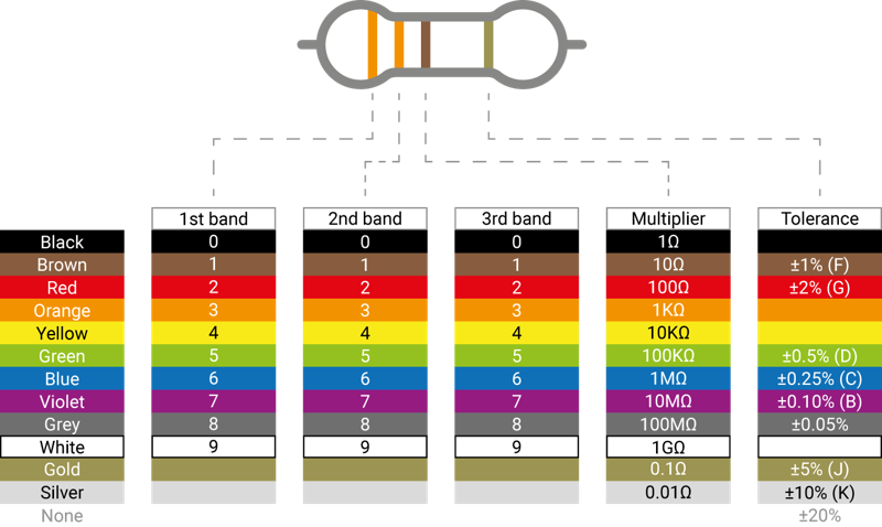
To read the value of a resistor, position it so the group of bands is to the left and the lone band is to the right. Starting from the first band, look its colour up in the ‘1st/2nd Band’ column of the table to get the first and second digits. This example has two orange bands, which both mean a value of ‘3’ for a total of ‘33’. If your resistor has four grouped bands instead of three, note down the value of the third band too (for five/six-band resistors, see rptl.io/5-6-band).
Moving onto the last grouped band — the third or fourth — look its colour up in the ‘Multiplier’ column. This tells you what you need to multiply your current number by to get the actual value of the resistor. This example has a brown band, which means ‘×101’. That may look confusing, but it’s simply scientific notation: ‘×101’ simply means ‘add one zero to the end of your number’. If it were blue, for ×106’, you would add six zeroes instead.
Taking 33 from the orange bands, plus the added zero from the brown band, gives us 330 — which is the value of the resistor, measured in ohms. The final band, the one on the right, is the tolerance of the resistor. This is simply how close to its rated value it is likely to be. Cheaper resistors might have a silver band, indicating a tolerance 10% higher or lower than its rating, or no last band at all, indicating a tolerance 20% higher or lower. The most expensive resistors have a grey band, indicating a tolerance within 0.05% of its rating. For hobbyist projects, accuracy isn’t that important: any tolerance will usually work fine.
If your resistor value goes above 1000 ohms (1000Ω), it is usually rated in kilohms (kΩ); if it goes above a million ohms, those are megohms (MΩ). A 2200Ω resistor would be written as 2.2 kΩ; a 2,200,000Ω resistor would be written as 2.2 MΩ.