Lesson 3
Breadboards and forward voltage
Build circuits 5 and 6 in Tinkercad before reading past the figures. These are the first two you’ll also rebuild with real parts — keep that in mind as you wire them; a breadboard mistake here is one you’ll actually have to find with your hands later.
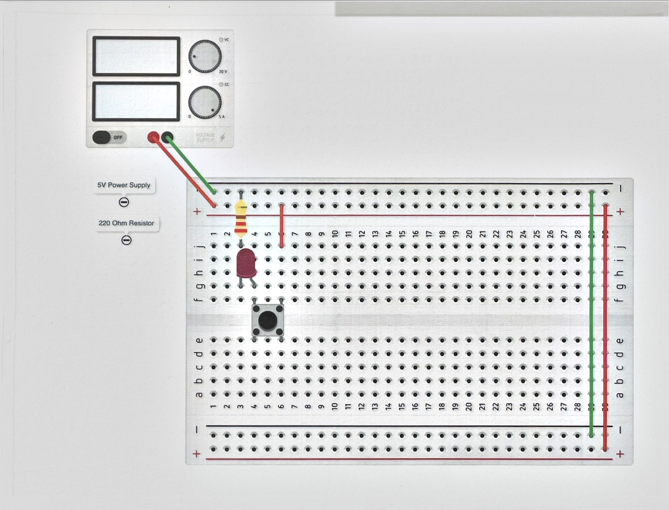
Same circuit, now as physical layout
Every circuit so far has been drawn as loose parts connected by wires that go wherever you want. Diagram 5 is the same LED-button-resistor circuit from the last lesson, but drawn as it actually sits on a breadboard.
That’s a different reading skill. On a breadboard, the two long rows along each edge (the rails) are each one continuous connection end to end — used for power and ground. The short rows in the middle are each one connection too, but only across five holes, split into two halves by the center channel. Two components in the same short row are connected to each other; two components one row apart are not connected at all unless you wire them together. Build diagram 5 by matching holes to the picture, not by copying the general shape.
Four colors, one resistor, one question
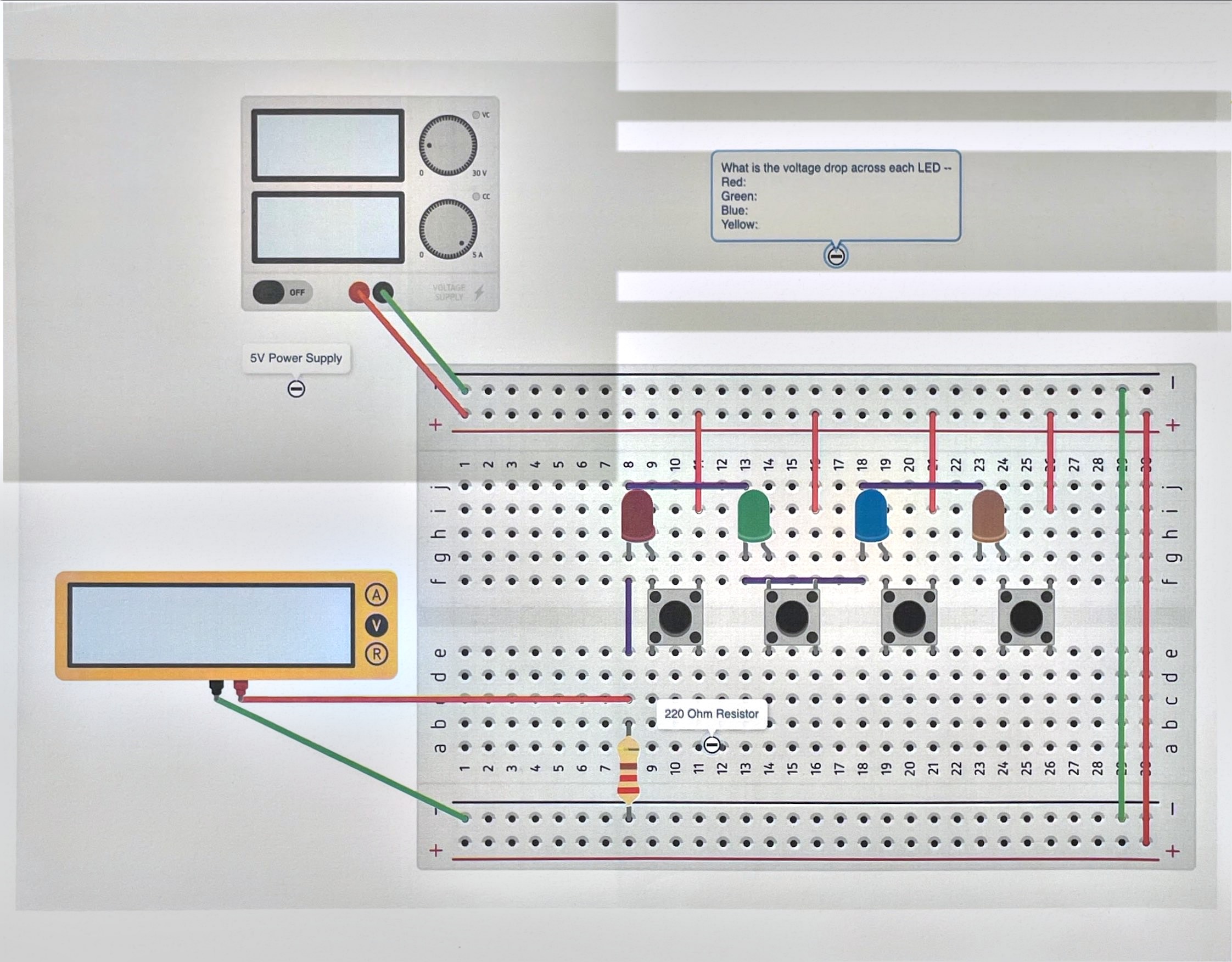
Diagram 6 wires four LEDs — red, green, blue, yellow — each behind its own button, sharing a single 220 Ω resistor. Press one button at a time and measure across the LED itself, not across the resistor. Write your prediction for each color before you measure. Fill in the Tinkercad column on the checkoff sheet now; you’ll fill in the Real column when you rebuild this with actual parts.
You’ll find the four colors don’t read the same voltage. An LED isn’t a resistor — it doesn’t obey Ohm’s law itself. Instead, it holds a roughly fixed voltage across it once current is flowing at all, called its forward voltage, and that fixed voltage is different for each color. Red tends to be lowest, blue highest, with yellow and green in between — compare your own numbers once you’ve measured them.
That fixed forward voltage is exactly why the resistor is there, and why Ohm’s law from lesson 1 still applies — just not to the LED. The resistor carries whatever voltage is left over after the LED takes its share:
I = (supply − Vf) ÷ R
With a 5 V supply, a 220 Ω resistor, and a red LED at roughly 2.0 V forward voltage:
I = (5 V − 2.0 V) ÷ 220 Ω ≈ 13.6 mA
Swap in a blue LED with a higher forward voltage and there’s less voltage left over for the resistor, so less current flows — which is part of why different colors can look like different brightnesses even through the same resistor.
Rebuilding for real
Once diagrams 5 and 6 both work in the simulator and are signed off, rebuild them with an actual breadboard, LEDs, resistor, and button. Fill in the Real LED column on the checkoff sheet and compare it to your simulated numbers.
Questions
- Order the four LED colors by forward voltage, then order them by wavelength (red is longest, blue is shortest). What do you notice?
- Did your real LEDs match your Tinkercad measurements? If not, does that mean the simulation was wrong?