Lesson 2
Switches and potentiometers
Build circuits 3 and 4 before reading past the figures.
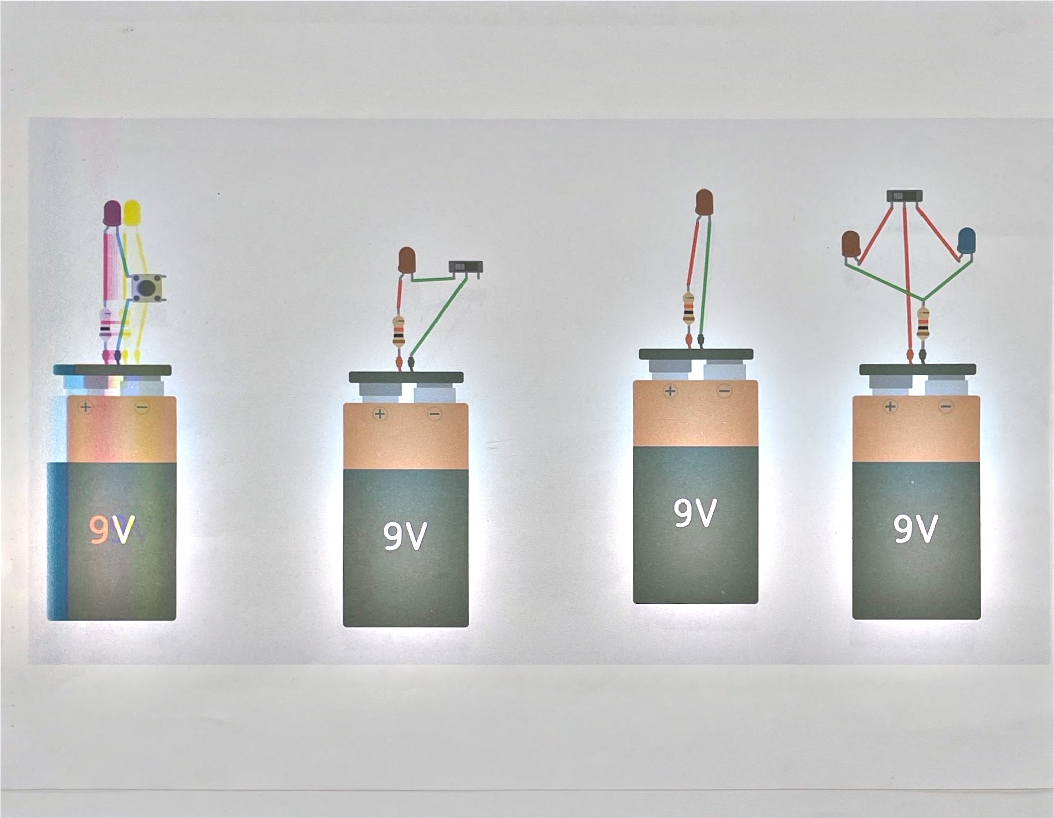
A switch is a break in the loop you control
Every circuit is a loop. Current only flows if the loop is complete from one battery terminal, through everything in between, back to the other terminal. A switch is just a deliberate gap in that loop — closed, the gap disappears; open, it doesn’t.
Circuit 3 on diagram 3 uses a pushbutton, which stays closed only while held — that’s why its LED lights only while you’re pressing it, not after you let go. The plain LED circuit on the far left has no switch at all: as soon as the battery’s connected, the loop is already complete and the LED is always on.
Notice every LED circuit on diagram 3 has a resistor in series except the button circuit at far left, which pairs two LEDs with one resistor and one switch. LEDs don’t limit their own current the way a resistor does — wire one straight across a 9V battery with nothing in series and you’ll burn it out fast. A resistor’s job here is to hold the current down to something the LED can survive. You’ll measure exactly how much in the next lesson.
LEDs also only work one way around. If a circuit isn’t lighting and the wiring looks right, that’s the first thing to check.
Resistance that isn’t fixed
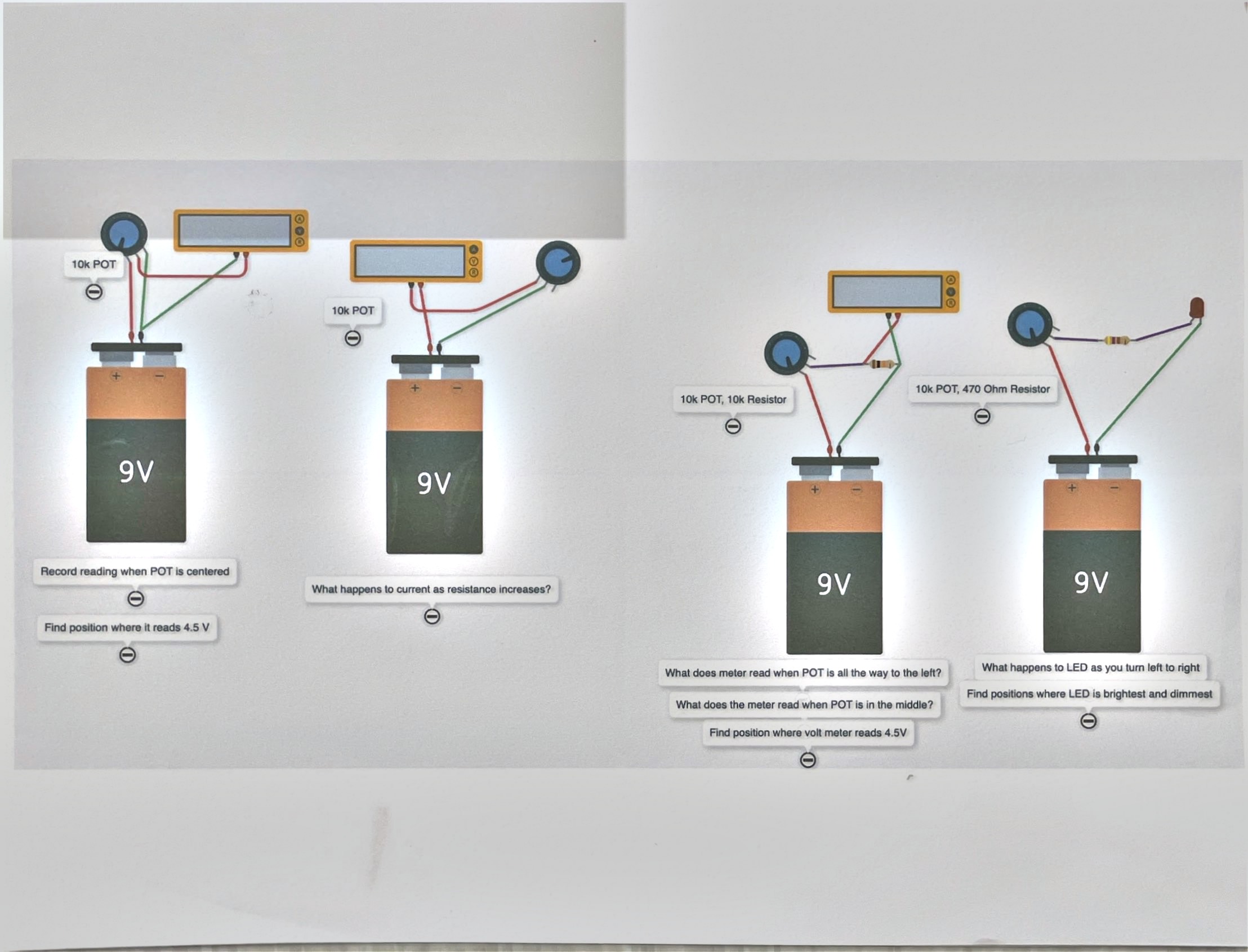
Every resistor you built with in the last lesson had one value, stamped on the part. A potentiometer — the “10k POT” in diagram 4 — is a resistor you can turn, sweeping continuously between 0 Ω and its labeled maximum (10 kΩ here) as the knob moves.
Build the first two circuits in diagram 4 and turn the knob while watching the meter. The voltmeter circuit shows the voltage across part of the potentiometer changing as you turn it; the ammeter circuit shows current changing too. Same battery, same idea as circuit 4 from last lesson — just now the resistance itself is the variable instead of being fixed by the part you picked.
The last two circuits pair a potentiometer with a fixed resistor and either a meter or an LED. Find the knob position that gives exactly 4.5 V on the third circuit, and note where the meter reads with the knob turned all the way to each side first — that range is your starting point for finding it. Watch the LED on the fourth circuit change brightness as you turn its potentiometer; brightness follows current, and current follows resistance, exactly the way Ohm’s law from the last lesson says it should.
Questions
- Why does the plain LED circuit on diagram 3 need a resistor at all if nothing in the circuit is switching?
- On diagram 4’s third circuit, is 4.5 V exactly in the middle of the knob’s travel, or does that depend on the fixed resistor paired with it?