Lesson 1
Voltage and current
Build circuits 1 and 2 from the printed diagrams before reading past the figures. Get every meter reading matching, then come back here.
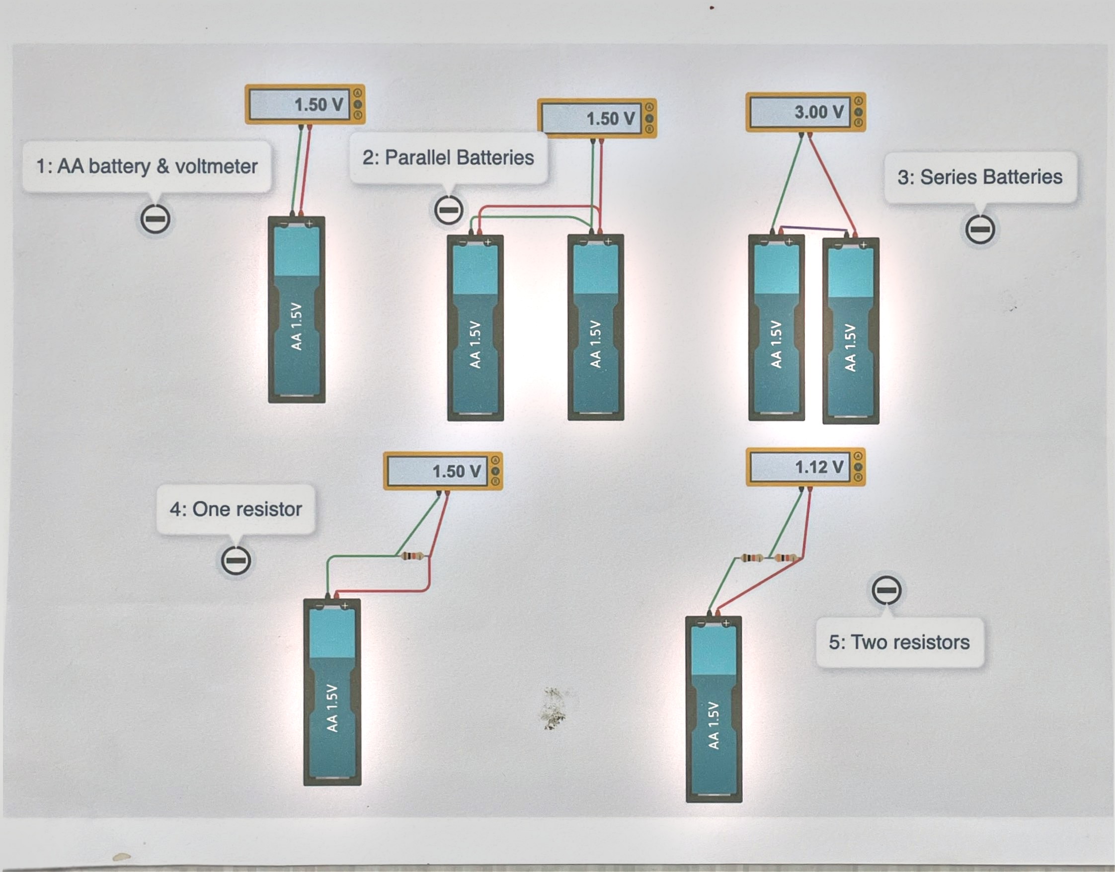
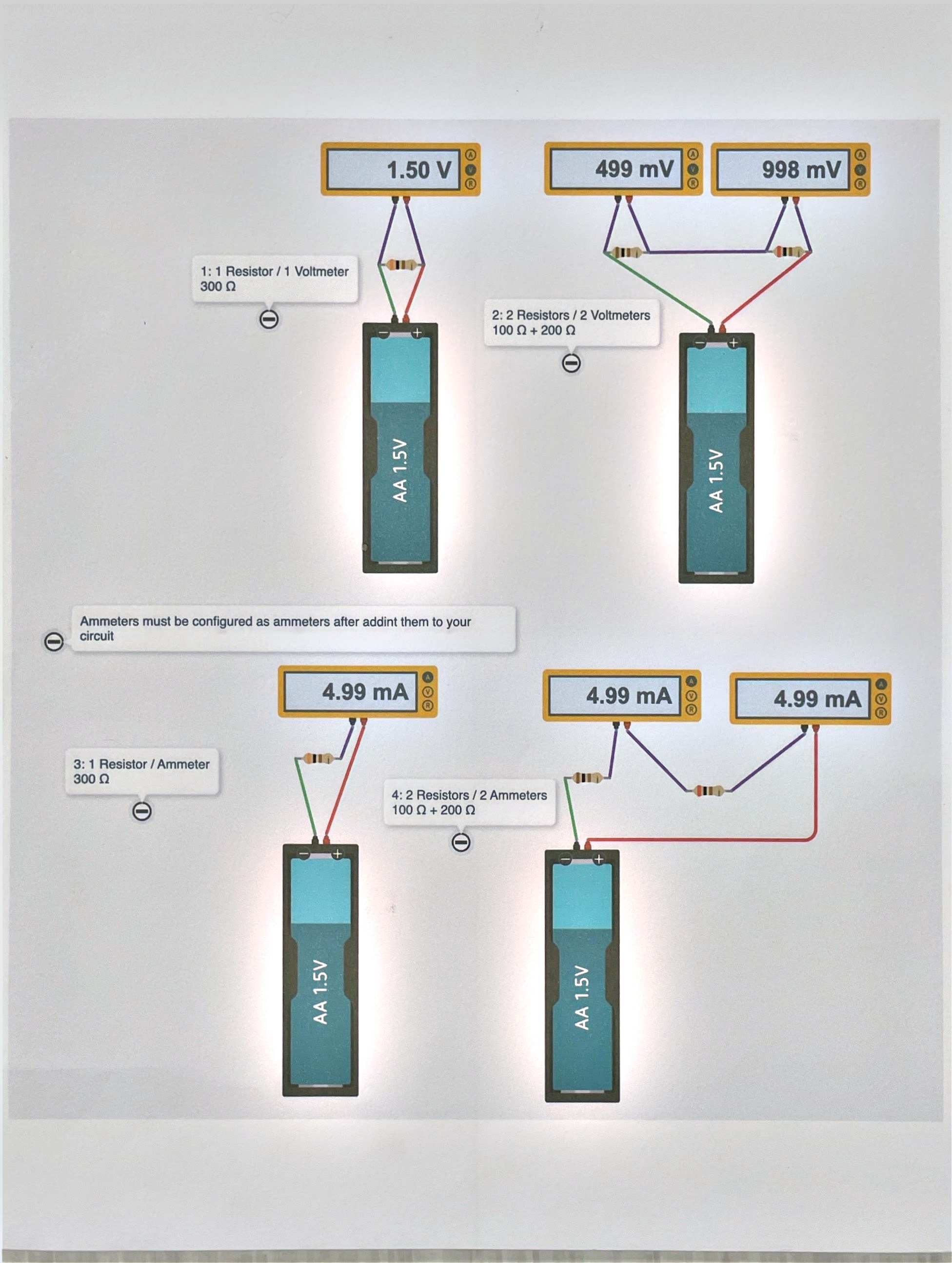
Voltage is measured across, current is measured through
That’s the whole difference between these two diagrams. Same batteries, same resistors, same layout — diagram 1 puts a meter across something, diagram 2 puts a meter in the path of something.
Look at what that difference does to the readings. In diagram 1, two AA batteries in parallel still read 1.50 V — adding a second cell in parallel gives you more current capacity, not more voltage. Wired in series instead, the same two cells read 3.00 V. Voltage sources add when you stack them end to end; they don’t add when you just wire them side by side.
The last two circuits in diagram 1 put one resistor, then two resistors in series, across a battery. The two-resistor circuit reads 1.12 V — less than the battery’s 1.50 V. That’s not a meter error. Getting to the bottom of that number is the point of this lesson.
Same circuit, other meter
Diagram 2 rebuilds the one-resistor and two-resistor circuits from diagram 1, but swaps the voltmeter for an ammeter. The one-resistor circuit (300 Ω) reads 4.99 mA. The two-resistor circuit (100 Ω + 200 Ω) also reads 4.99 mA on both ammeters — one on either side of the two resistors.
Sit with that for a second: the current is the same everywhere in that loop, on both sides of both resistors. Current doesn’t get “used up” as it flows past a resistor — voltage does.
Questions
- Two batteries in parallel and two batteries in series both use two AA cells. Why doesn’t the parallel pair read 3.00 V too?
- The two-resistor circuit had the same current through both resistors but different voltages across them. Could a circuit ever have the same voltage across two different resistors instead? What would that take?