← MicroPython on Raspberry Pi Pico
Lesson 5
Traffic light controller
Create your own mini pedestrian crossing system with multiple LEDs and a push-button
Microcontrollers can be found in almost all the electronic items you use on a daily basis — including traffic lights. A traffic light controller is a specially-built system which changes the lights on a timer, watches for pedestrians looking to cross, and can even adjust the timing of the lights depending on how much traffic there is — talking to nearby traffic light systems to ensure the whole traffic network keeps flowing smoothly.
While building a large-scale traffic management system is a pretty advanced project, it’s simplicity itself to build a miniature simulator powered by your Pico-family device. With this project, you’ll see how to control multiple LEDs, set different timings, and how to monitor a push-button input while the rest of the program continues to run using a technique known as interrupts.
For this project, you’ll need your Pico; a breadboard; a red, yellow (or amber), and green LED; three 330 Ω resistors; an active piezoelectric buzzer; and a selection of male-to-male (M2M) jumper wires. You’ll also need a micro USB cable to connect your Pico to your computer.
A simple traffic light
Disconnect your Pico from USB, and build the traffic light system shown in Figure 5-1. Take your red LED and insert it into the breadboard so it straddles the centre divide. Use one 330 Ω resistor, and a jumper wire if you need to make a longer connection, to connect the longer leg — the anode — of the LED to the pin at the bottom-right of your Pico as seen from the top with the micro USB cable leftmost, GP15. If you’re using a numbered breadboard and have your Pico inserted as shown, this will be column 20.
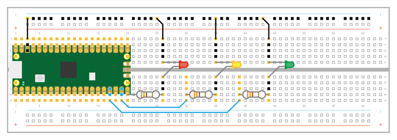
Take a jumper wire and connect the shorter leg — the cathode — of the red LED to your breadboard’s ground rail. Take another, and connect the ground rail to one of your Pico’s ground (GND) pins — in Figure 5-1, we’ve used the ground pin on column three of the breadboard.
You’ve now got one LED connected to your Pico, but a real traffic light has at least three in all: a red light to tell the traffic to stop, amber or yellow to tell the traffic the light is about to change, and green to tell the traffic it can go again.
Take your amber or yellow LED and wire it to your Pico in the same way as the red LED, making sure the shorter leg connected to the ground rail of the breadboard. This time, though, wire the longer leg — via the 330 Ω resistor — to the pin next to the one to which you wired the red LED, GP14.
Finally, take the green LED and wire it up the same way again — remembering the 330 Ω resistor — to pin GP13. This isn’t the pin right next to pin GP14, though — that pin is a ground (GND) pin, which you can see if you look closely at your Pico: the ground pins all have a square shape to their pads, while the other pins are round.
When you’ve finished, your circuit should match Figure 5-1: a red, a yellow or amber, and a green LED, all wired to different GPIO pins on your Pico via individual 330 Ω resistors and connected to a shared ground pin via your breadboard’s ground rail.
To program your traffic lights, connect your Pico to ViperIDE. Create a new program, and start by importing the machine library so you can control your Pico’s GPIO pins:
import machine
You’ll also need to import the time library, so you can add delays between the lights going on and off:
import time
As with any program using your Pico’s GPIO pins, you’ll need to set each pin up before you can control it:
led_red = machine.Pin(15, machine.Pin.OUT)
led_amber = machine.Pin(14, machine.Pin.OUT)
led_green = machine.Pin(13, machine.Pin.OUT)
These lines set pins GP15, GP14, and GP13 up as outputs, and each is given a descriptive name to make it easier to read the code: led, so you know the pins control an LED, and then the colour of the LED.
Real traffic lights don’t run through once and stop — they keep going, even when there’s no traffic there and everyone’s asleep. So that your program does the same, you’ll need to set up an infinite loop:
while True:
You’ll need to indent all the lines beneath this by four spaces, so MicroPython knows they form part of the loop; your editor should automatically indent the next line for you when you press Enter.
    led_red.value(1)
    time.sleep(5)
    led_amber.value(1)
    time.sleep(2)
    led_red.value(0)
    led_amber.value(0)
    led_green.value(1)
    time.sleep(5)
    led_green.value(0)
    led_amber.value(1)
    time.sleep(5)
    led_amber.value(0)
Save the program to your Pico as Traffic_Lights.py and click the Run icon. Watch the LEDs: red lights up first, telling traffic to stop; next, amber comes on to warn drivers the lights are about to change; then both switch off and green comes on to let traffic know it can pass; then green turns off and amber comes on to warn drivers the lights are about to change again; finally, amber turns off — and the loop restarts from the beginning, with red coming on.
The pattern will loop until you stop the program, because it forms an infinite loop. It’s based on the traffic light pattern used in real-world traffic control systems in the UK and Ireland, but sped up — giving cars just five seconds to pass through the lights wouldn’t let the traffic flow very freely!
Real traffic lights aren’t just there for road vehicles, though: they are also there to protect pedestrians, giving them an opportunity to cross a busy road safely. In the UK, the most common type of these lights are known as pedestrian-operated user-friendly intelligent crossings or puffin crossings.
To turn your traffic lights into a puffin crossing, you’ll need two things: a push-button switch, so the pedestrian can ask the lights to let them cross the road; and a buzzer, so the pedestrian knows when it’s their turn to cross. Wire those into your breadboard as in Figure 5-2, with the switch wired to pin GP16 and the ground rail of your breadboard, and the buzzer wired to pin GP12 and the breadboard’s ground rail. Disconnect the Pico from USB while you build this.
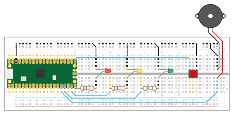
If you run your program again, you’ll find the button and buzzer do nothing. That’s because you haven’t yet told your program how to use them. Go back to the lines where you initialised your LEDs and add two lines below:
button = machine.Pin(16, machine.Pin.IN, machine.Pin.PULL_UP)
buzzer = machine.Pin(12, machine.Pin.OUT)
This sets the button on pin GP16 up as an input, and the buzzer on pin GP12 as an output. Remember, your Raspberry Pi Pico has built-in programmable resistors for its inputs, which we are setting to pull-up mode for the projects in this book. This means that the pin’s voltage is pulled up to 3.3V (and its logic level is 1), unless it is connected to a GND pin (in which case its logic level will be 0 until disconnected).
Next, you need a way for your program to constantly monitor the value of the button. Previously, all your programs have worked step-by-step through a list of instructions — only ever doing one thing at a time. Your traffic light program is no different: as it runs, MicroPython walks through your instructions step-by-step, turning the LEDs on and off.
For a basic set of traffic lights, that’s enough; for a puffin crossing, though, your program needs to be able to record whether the button has been pressed in a way that doesn’t interrupt the traffic lights. To make that work, you’ll need a new approach: interrupt requests (IRQs).
The name sounds complex, but it’s simple: imagine you’re reading a book, page by page, and someone comes up to you and asks you a question. That person is performing an interrupt request: asking you to stop what you’re doing, answer their question, then letting you go back to reading your book.
A MicroPython interrupt request works in the same way: it allows something, in this case the press of a push-button switch, to interrupt the main program. To set up an interrupt, you need two things: the interrupt itself, and a handler or callback function**. Start with the handler first by adding the following lines to your program:
button_pressed = False

def btn_handler(pin):
    global button_pressed
    if not button_pressed:
        button_pressed = True
The first line creates a new variable to track whether the button has been pressed or not and sets it to False — meaning when the program starts, the button hasn’t yet been pushed. The next section defines the handler for your interrupt: when the interrupt is requested, the three indented lines will run. There’s no loop here, so the code will only run once — but if you press the button again, the code will run again.
The first of the indented lines turns the button_pressed variable into a global variable. The variables you’ve been working with prior to this are known as local variables, and only work in one section of your program; a global variable works everywhere, meaning one function can change the value and another can check to see if it has been changed even if they’re running in two separate sections of your program.
The next line checks to see if code has already run, by checking the state of the button_pressed variable. If it’s been set to True , because the button has already been pressed, the next line won’t run; only if it’s set to False , and hasn’t already been pushed, will the final line run to set the variable to True .
If you were to run your program now, the button wouldn’t do anything. That’s because you have a handler, but no trigger : pressing the button doesn’t make the interrupt request, and the handler never runs. To fix that, you need to add a new line to your program:
button.irq(trigger=machine.Pin.IRQ_FALLING, handler=btn_handler)
The trigger tells your Pico what it should be looking for as a valid signal to interrupt what it’s doing; the handler, which you defined earlier in your program, is the code which runs after the interrupt is triggered.
In this program your trigger is IRQ_FALLING: this triggers the interrupt when the pin’s value falls from high — its default state, thanks to the built-in pull-up resistor — to low, when the button connected to GND is pushed. A trigger of IRQ_RISING would do the opposite: trigger the interrupt when the pin goes from low to high. In the case of your circuit, IRQ_FALLING triggers as soon as the button is pushed; IRQ_RISING triggers only when the button is released.
Click the Run button now. You’ll see the traffic lights carry on their pattern exactly as before, with no delay or pauses. If you press the button, though, nothing will happen — because you haven’t added the code to actually react to the button yet.
Go to the start of your main loop, and add the following code directly underneath the line while True: — remembering to pay attention to the nested indentation, and deleting any indentation your editor added when it’s no longer required:
if button_pressed == True:
    led_red.value(1)
    for i in range(20):
        buzzer.value(1)
        time.sleep(0.05)
        buzzer.value(0)
        time.sleep(0.2)
    button_pressed = False
This chunk of code checks the button_pressed global variable to see if the push-button switch has been pressed at any time since the loop last ran. If it has, as reported by the button-reading handler you made earlier, it begins running a section of code which starts by turning the red LED on to stop traffic and then beeps the buzzer 20 times — letting the pedestrian know it’s time to cross.
Finally, the last line reset the button_pressed variable back to False — so the next time the loop runs it won’t trigger the pedestrian crossing code unless the button has been pushed again.
Your program should now look like this:
import machine
import time

led_red = machine.Pin(15, machine.Pin.OUT)
led_amber = machine.Pin(14, machine.Pin.OUT)
led_green = machine.Pin(13, machine.Pin.OUT)
button = machine.Pin(16, machine.Pin.IN, machine.Pin.PULL_UP)
buzzer = machine.Pin(12, machine.Pin.OUT)

button_pressed = False

def btn_handler(pin):
    global button_pressed
    if not button_pressed:
        button_pressed = True

button.irq(trigger=machine.Pin.IRQ_FALLING, handler=btn_handler)

while True:
    if button_pressed == True:
        led_red.value(1)
        for i in range(20):
            buzzer.value(1)
            time.sleep(0.05)
            buzzer.value(0)
            time.sleep(0.2)
        button_pressed = False
    led_red.value(1)
    time.sleep(5)
    led_amber.value(1)
    time.sleep(2)
    led_red.value(0)
    led_amber.value(0)
    led_green.value(1)
    time.sleep(5)
    led_green.value(0)
    led_amber.value(1)
    time.sleep(5)
    led_amber.value(0)
Click the Run icon. At first, the program will run as normal: the traffic lights will go on and off in the usual pattern. Press the push-button switch: if the program is currently in the middle of its loop, nothing will happen until it reaches the end and loops back around again — at which point the light will go red and the buzzer will beep to let you know it’s safe to cross the road.
The conditional section of code for crossing the road runs before the code you wrote earlier for turning the lights on and off in a cyclic pattern: after it’s finished, the pattern will begin as usual with the red LED staying lit for a further five seconds on top of the time it was lit while the buzzer was going. This mimics how a real puffin crossing works: the red light remains lit even after the buzzer has stopped sounding, so anyone who started to cross the road while the buzzer was going has time to reach the other side before the traffic is allowed to go.
Let the traffic lights loop through their cycle a few more times, then press the button again to trigger another crossing. Congratulations: you’ve built your own puffin crossing!