Lesson 5
Connect a Microbit
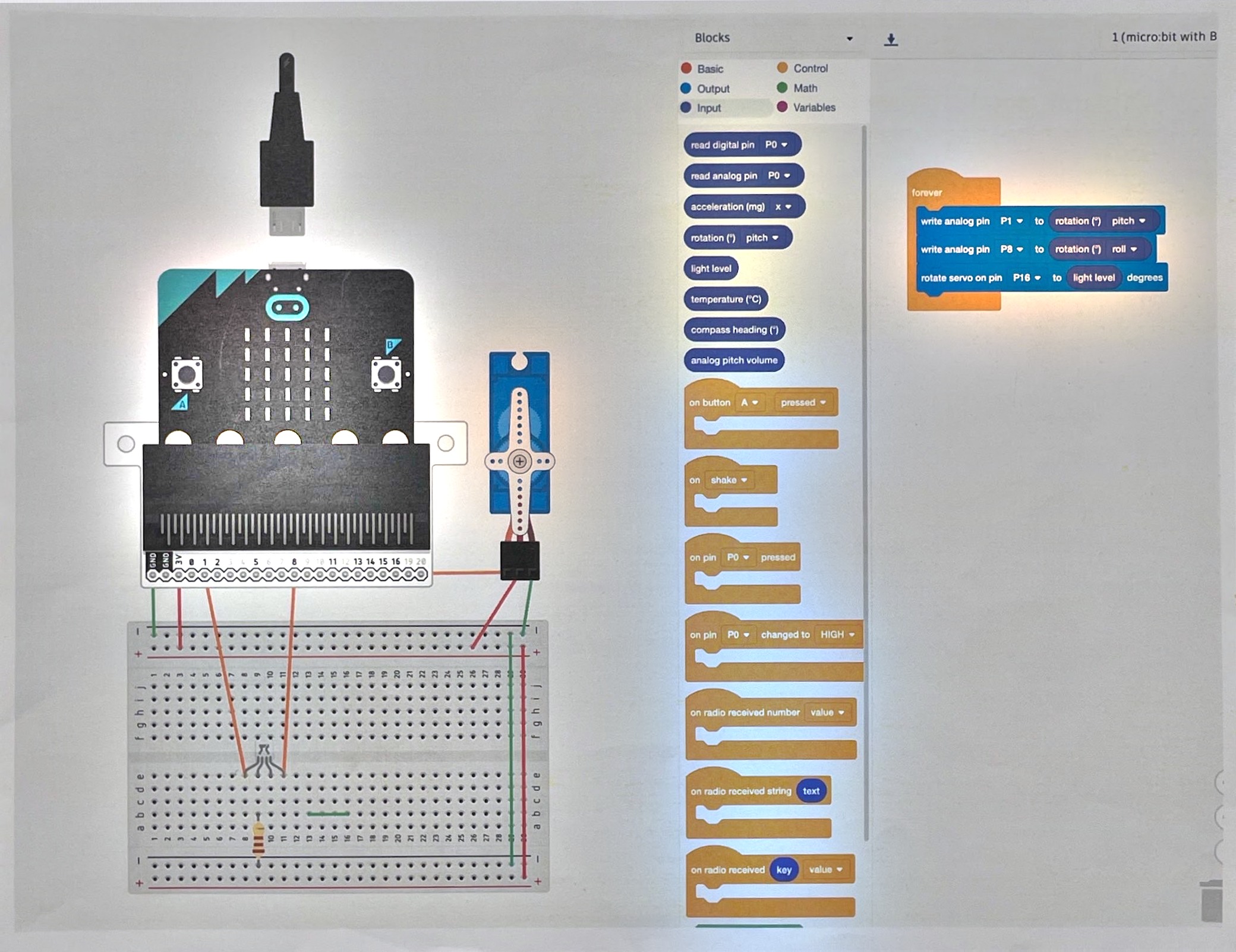
Build circuits 8 and 9 with a micro:bit and MakeCode before reading past the figures. Both use blocks, not typed code.
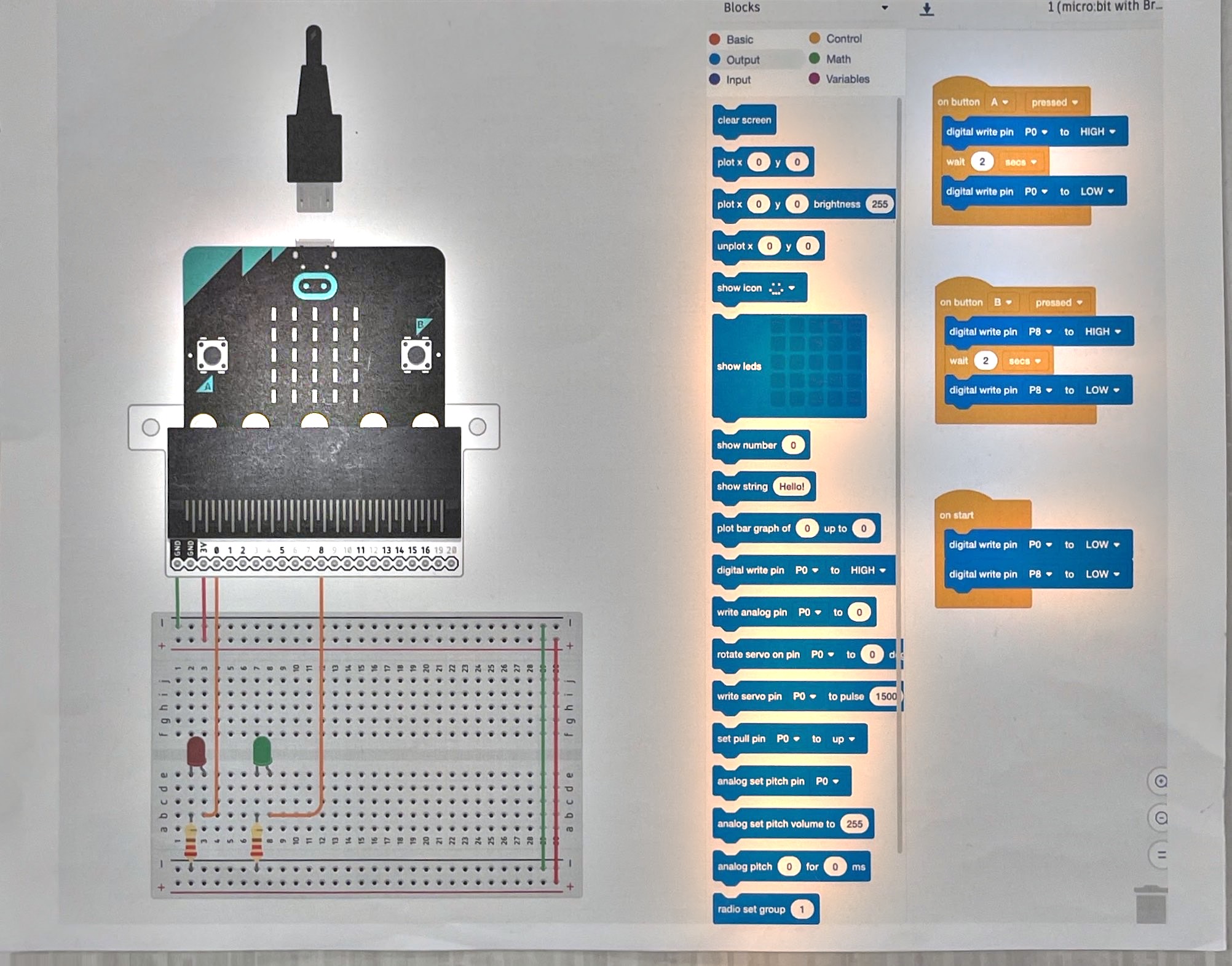
A program is a break in the loop it controls
Lesson 2 was a switch: a person closes the loop. Lesson 4 was a
photoresistor: the room closes the loop. Diagram 8 is the same loop again,
closed by a program instead — button A pressed calls for pin P0 high, waits
2 seconds, then sets it low again; button B does the same on pin P8. The
on start block sets both pins low before anything else runs, so the LEDs
begin off rather than in whatever state the pins happened to power up in.
The loop being closed by code rather than a finger doesn’t change what’s happening electrically. It’s still current flowing because a pin went high, same as every LED circuit before this one — it’s only the decider that changed.
Code can do more than open and shut
A switch or a button is binary: open or closed, on or off. Diagram 9 shows
code doing something neither a switch nor a photoresistor can — a forever
loop continuously reads the micro:bit’s own tilt (pitch and roll) and
writes it as an analog value to an LED, while separately reading the light
sensor and using it to aim a servo, rather than just switching it on.
Code can turn one input into a different, continuously varying output — not
just open and shut a loop, but decide where a loop points.
That’s the honest end of this sequence: a model — Ohm’s law, power, all of it — is trustworthy inside the assumptions it was built on, and silent outside them. Eight circuits in, you’ve earned the right to be told that.
Questions
- Diagram 8’s LEDs are switched fully on or fully off. Diagram 9’s LED is driven by an analog write instead. What can an analog write do that a digital write on diagram 8 can’t?
- If a robot’s motor and its controller board share a power supply, and the motor draws a current spike, what happens to the controller?