How this works
Nine circuits, each one building on the last. You build every one in Tinkercad Circuits before anyone explains anything.
Before you start: kilo and milli
The meters in these diagrams don’t read in plain volts, amps, and ohms — they read 499 mV, 4.99 mA, 10 kΩ. If milli and kilo aren’t automatic for you yet, those numbers will slow you down before you even get to the electronics.
You already have the skill: it’s the same one behind mm, cm, and km. Read Kilo & Milli: Borrowing the Meter Stick to Teach Electrical Units first — it’s the same milli-means-÷1000, kilo-means-×1000 rule you already use for length, just pointed at volts, amps, and ohms instead.
Build first, discuss after
You’ll get a printed diagram, not a shared Tinkercad file. Open a blank workspace and build the circuit from the picture. Reading a diagram and turning it into a working circuit is most of the skill being taught here — opening a ready-made file would skip the part that matters.
Work through all nine in the simulator. Once a circuit matches its “done when” condition on the checkoff sheet, get it signed off. Only after it’s working will we talk through what’s actually going on in the circuit — what changed from the last diagram, and why it behaves the way it does. If you’re stuck, that conversation happens early for you; if you’re not, it happens once you’re done.
Predict, then measure
Several circuits ask you to predict a reading before you take it. Write the prediction down first. Being wrong is fine and often more useful than being right — it’s the gap between your prediction and the meter that’s worth talking about.
Voltage and current
Build circuits 1 and 2 from the printed diagrams before reading past the figures. Get every meter reading matching, then come back here.
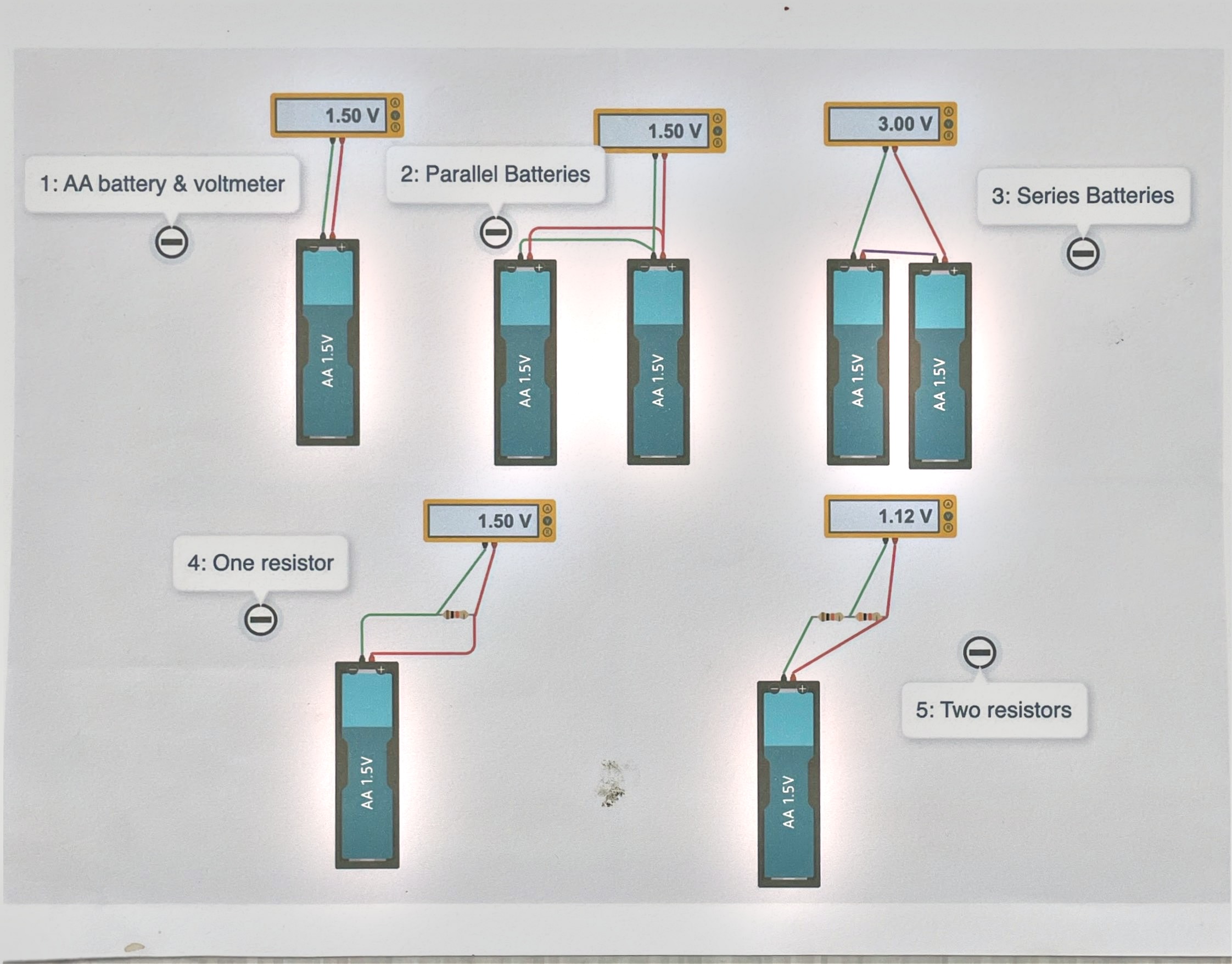
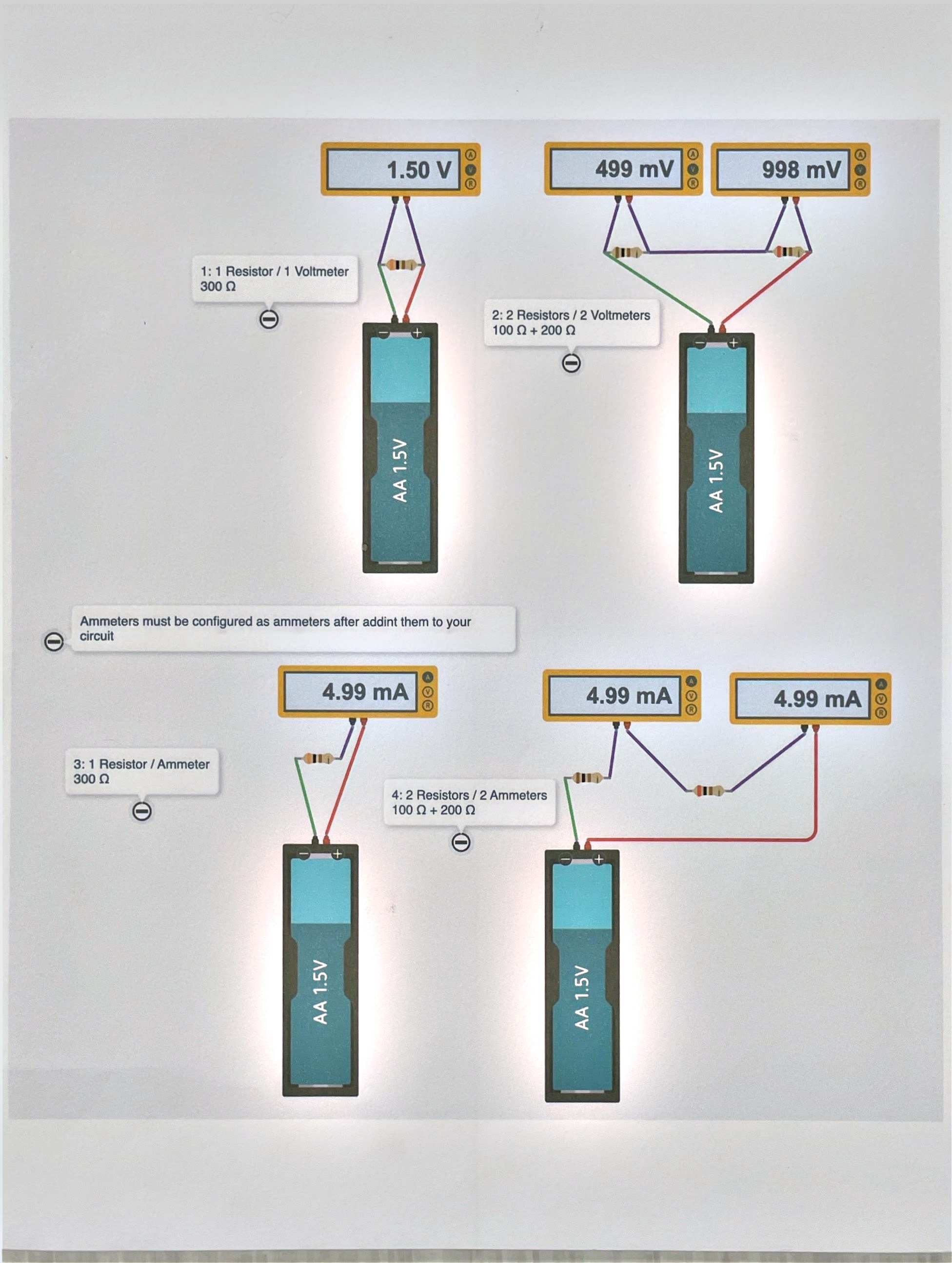
Voltage is measured across, current is measured through
That’s the whole difference between these two diagrams. Same batteries, same resistors, same layout — diagram 1 puts a meter across something, diagram 2 puts a meter in the path of something.
Look at what that difference does to the readings. In diagram 1, two AA batteries in parallel still read 1.50 V — adding a second cell in parallel gives you more current capacity, not more voltage. Wired in series instead, the same two cells read 3.00 V. Voltage sources add when you stack them end to end; they don’t add when you just wire them side by side.
The last two circuits in diagram 1 put one resistor, then two resistors in series, across a battery. The two-resistor circuit reads 1.12 V — less than the battery’s 1.50 V. That’s not a meter error. Getting to the bottom of that number is the point of this lesson.
Same circuit, other meter
Diagram 2 rebuilds the one-resistor and two-resistor circuits from diagram 1, but swaps the voltmeter for an ammeter. The one-resistor circuit (300 Ω) reads 4.99 mA. The two-resistor circuit (100 Ω + 200 Ω) also reads 4.99 mA on both ammeters — one on either side of the two resistors.
Sit with that for a second: the current is the same everywhere in that loop, on both sides of both resistors. Current doesn’t get “used up” as it flows past a resistor — voltage does.
Questions
- Two batteries in parallel and two batteries in series both use two AA cells. Why doesn’t the parallel pair read 3.00 V too?
- The two-resistor circuit had the same current through both resistors but different voltages across them. Could a circuit ever have the same voltage across two different resistors instead? What would that take?
Switches and potentiometers
Build circuits 3 and 4 before reading past the figures.
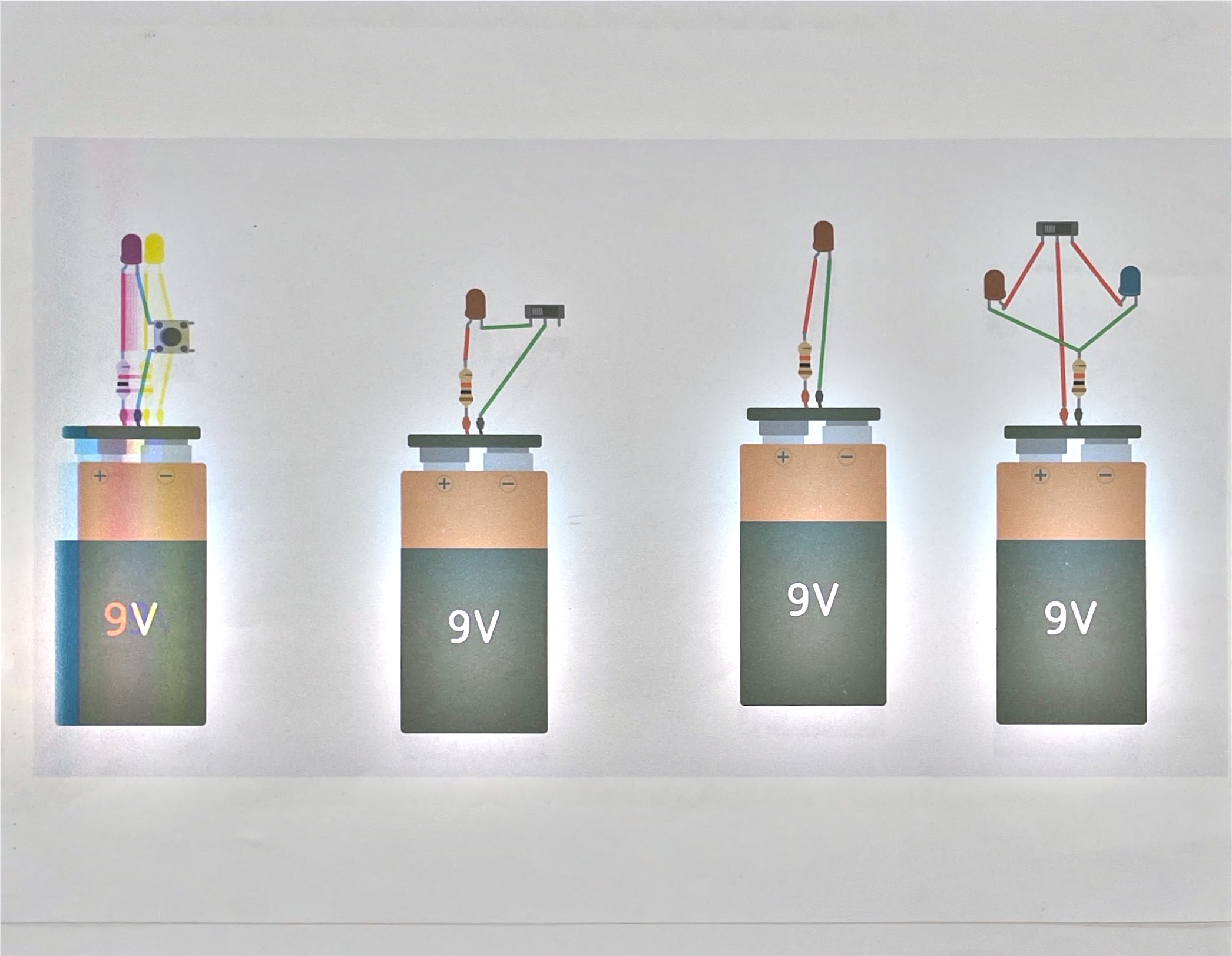
A switch is a break in the loop you control
Every circuit is a loop. Current only flows if the loop is complete from one battery terminal, through everything in between, back to the other terminal. A switch is just a deliberate gap in that loop — closed, the gap disappears; open, it doesn’t.
Circuit 3 on diagram 3 uses a pushbutton, which stays closed only while held — that’s why its LED lights only while you’re pressing it, not after you let go. The plain LED circuit on the far left has no switch at all: as soon as the battery’s connected, the loop is already complete and the LED is always on.
Notice every LED circuit on diagram 3 has a resistor in series except the button circuit at far left, which pairs two LEDs with one resistor and one switch. LEDs don’t limit their own current the way a resistor does — wire one straight across a 9V battery with nothing in series and you’ll burn it out fast. A resistor’s job here is to hold the current down to something the LED can survive. You’ll measure exactly how much in the next lesson.
LEDs also only work one way around. If a circuit isn’t lighting and the wiring looks right, that’s the first thing to check.
Resistance that isn’t fixed
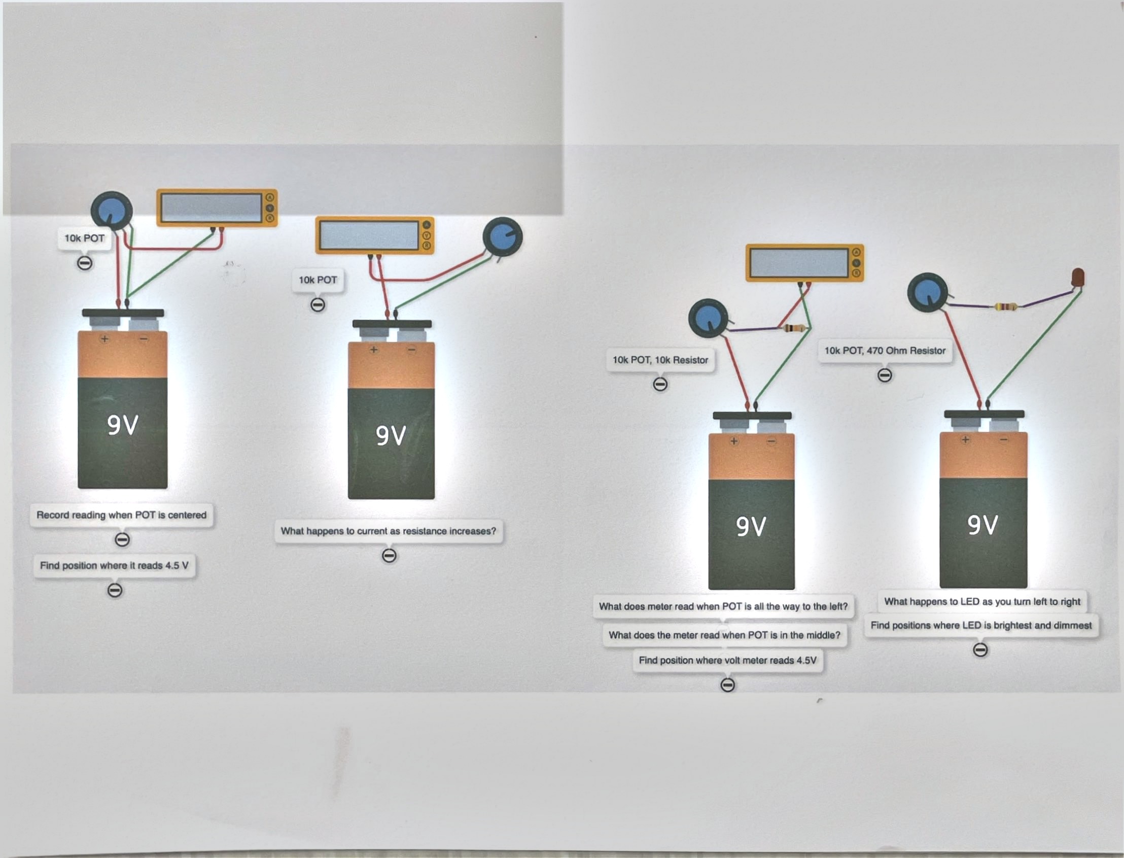
Every resistor you built with in the last lesson had one value, stamped on the part. A potentiometer — the “10k POT” in diagram 4 — is a resistor you can turn, sweeping continuously between 0 Ω and its labeled maximum (10 kΩ here) as the knob moves.
Build the first two circuits in diagram 4 and turn the knob while watching the meter. The voltmeter circuit shows the voltage across part of the potentiometer changing as you turn it; the ammeter circuit shows current changing too. Same battery, same idea as circuit 4 from last lesson — just now the resistance itself is the variable instead of being fixed by the part you picked.
The last two circuits pair a potentiometer with a fixed resistor and either a meter or an LED. Find the knob position that gives exactly 4.5 V on the third circuit, and note where the meter reads with the knob turned all the way to each side first — that range is your starting point for finding it. Watch the LED on the fourth circuit change brightness as you turn its potentiometer; brightness follows current, and current follows resistance, exactly the way Ohm’s law from the last lesson says it should.
Questions
- Why does the plain LED circuit on diagram 3 need a resistor at all if nothing in the circuit is switching?
- On diagram 4’s third circuit, is 4.5 V exactly in the middle of the knob’s travel, or does that depend on the fixed resistor paired with it?
Breadboards and forward voltage
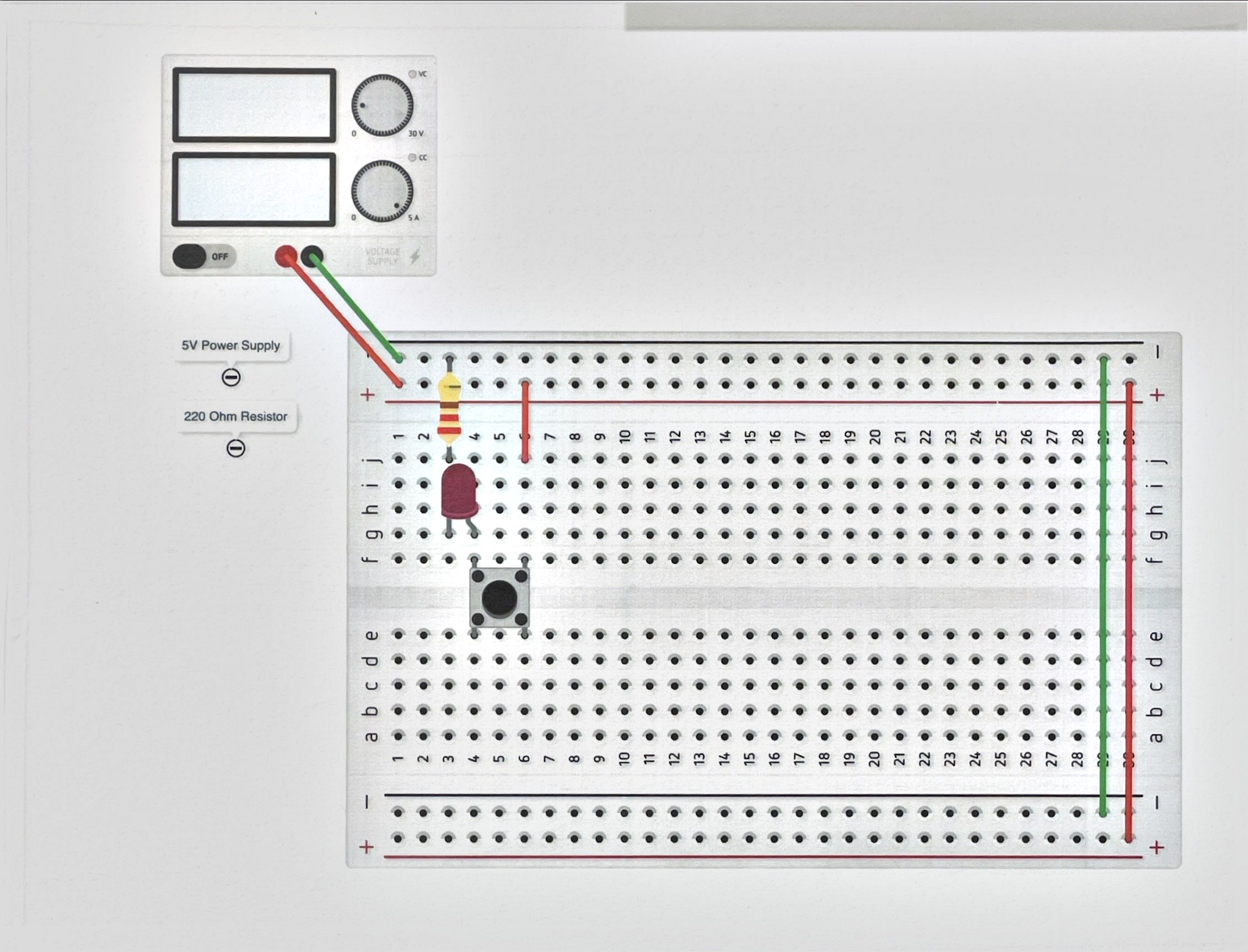
Build circuits 5 and 6 in Tinkercad before reading past the figures. These are the first two you’ll also rebuild with real parts — keep that in mind as you wire them; a breadboard mistake here is one you’ll actually have to find with your hands later.
Same circuit, now as physical layout
Every circuit so far has been drawn as loose parts connected by wires that go wherever you want. Diagram 5 is the same LED-button-resistor circuit from the last lesson, but drawn as it actually sits on a breadboard.
That’s a different reading skill. On a breadboard, the two long rows along each edge (the rails) are each one continuous connection end to end — used for power and ground. The short rows in the middle are each one connection too, but only across five holes, split into two halves by the center channel. Two components in the same short row are connected to each other; two components one row apart are not connected at all unless you wire them together. Build diagram 5 by matching holes to the picture, not by copying the general shape.
Four colors, one resistor, one question
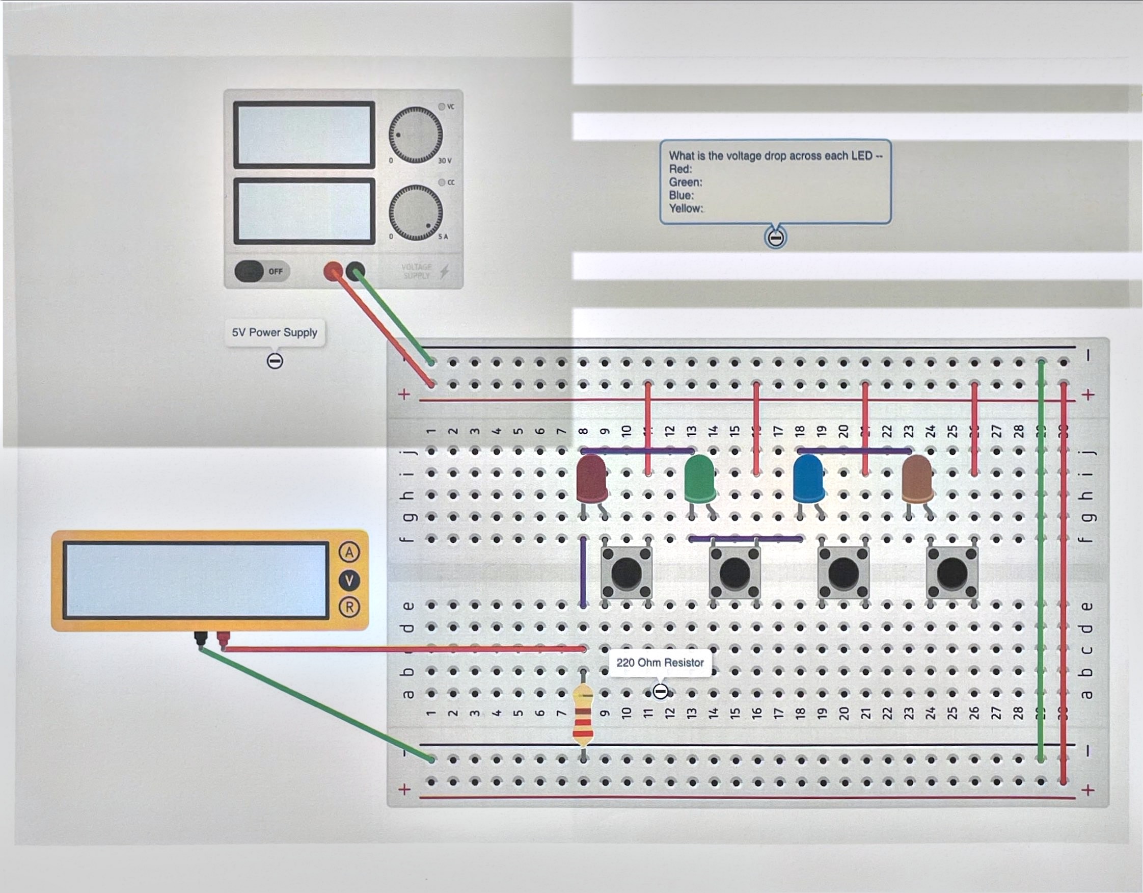
Diagram 6 wires four LEDs — red, green, blue, yellow — each behind its own button, sharing a single 220 Ω resistor. Press one button at a time and measure across the LED itself, not across the resistor. Write your prediction for each color before you measure. Fill in the Tinkercad column on the checkoff sheet now; you’ll fill in the Real column when you rebuild this with actual parts.
You’ll find the four colors don’t read the same voltage. An LED isn’t a resistor — it doesn’t obey Ohm’s law itself. Instead, it holds a roughly fixed voltage across it once current is flowing at all, called its forward voltage, and that fixed voltage is different for each color. Red tends to be lowest, blue highest, with yellow and green in between — compare your own numbers once you’ve measured them.
That fixed forward voltage is exactly why the resistor is there, and why Ohm’s law from lesson 1 still applies — just not to the LED. The resistor carries whatever voltage is left over after the LED takes its share:
I = (supply − Vf) ÷ R
With a 5 V supply, a 220 Ω resistor, and a red LED at roughly 2.0 V forward voltage:
I = (5 V − 2.0 V) ÷ 220 Ω ≈ 13.6 mA
Swap in a blue LED with a higher forward voltage and there’s less voltage left over for the resistor, so less current flows — which is part of why different colors can look like different brightnesses even through the same resistor.
Rebuilding for real
Once diagrams 5 and 6 both work in the simulator and are signed off, rebuild them with an actual breadboard, LEDs, resistor, and button. Fill in the Real LED column on the checkoff sheet and compare it to your simulated numbers.
Questions
- Order the four LED colors by forward voltage, then order them by wavelength (red is longest, blue is shortest). What do you notice?
- Did your real LEDs match your Tinkercad measurements? If not, does that mean the simulation was wrong?
Photoresistor
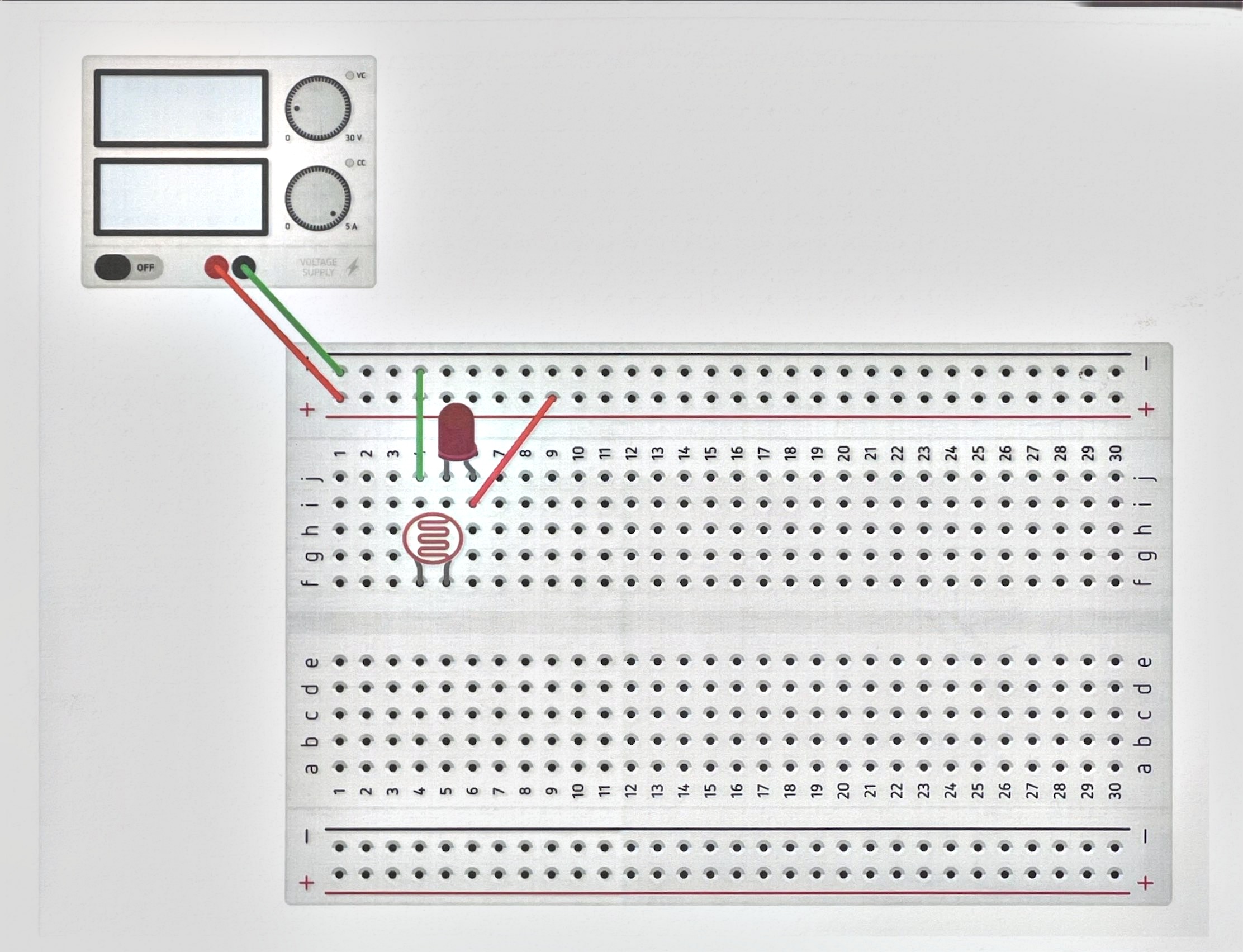
Build circuit 7 before reading past the figure.
A resistor the world turns
A potentiometer, from a couple of lessons back, is a resistor a person turns with a knob. A photoresistor is the same idea with a different hand on the dial: its resistance changes with the light falling on it, higher in the dark, lower in bright light. Wire it in place of a fixed resistor and you’ve built a light sensor out of a component with no electronics inside it at all.
Cover the photoresistor and watch the LED’s brightness change, the same way turning the potentiometer changed brightness in lesson 2. Nothing about the math is different — it’s still current set by resistance, Ohm’s law from lesson 1 still holds at every instant. The only thing that changed is who, or what, is adjusting the resistance: you, with a knob; the room, with its light level.
That’s the last piece of the pattern this whole sequence has been building: a switch is a break in the loop a person controls. A photoresistor is a break in the loop the world controls. Next lesson, you’ll build one a program controls.
Questions
- If you wanted the LED to get brighter as the room gets darker instead of dimmer, what would need to change in the circuit?
Connect a Microbit
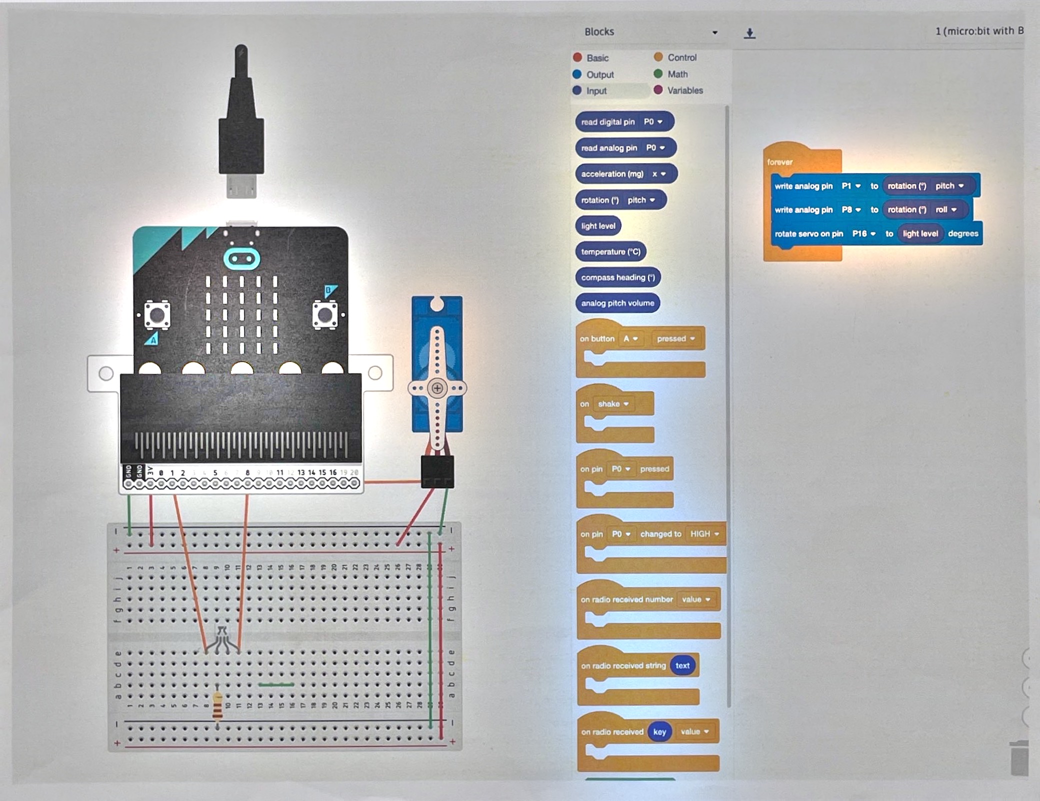
Build circuits 8 and 9 with a micro:bit and MakeCode before reading past the figures. Both use blocks, not typed code.
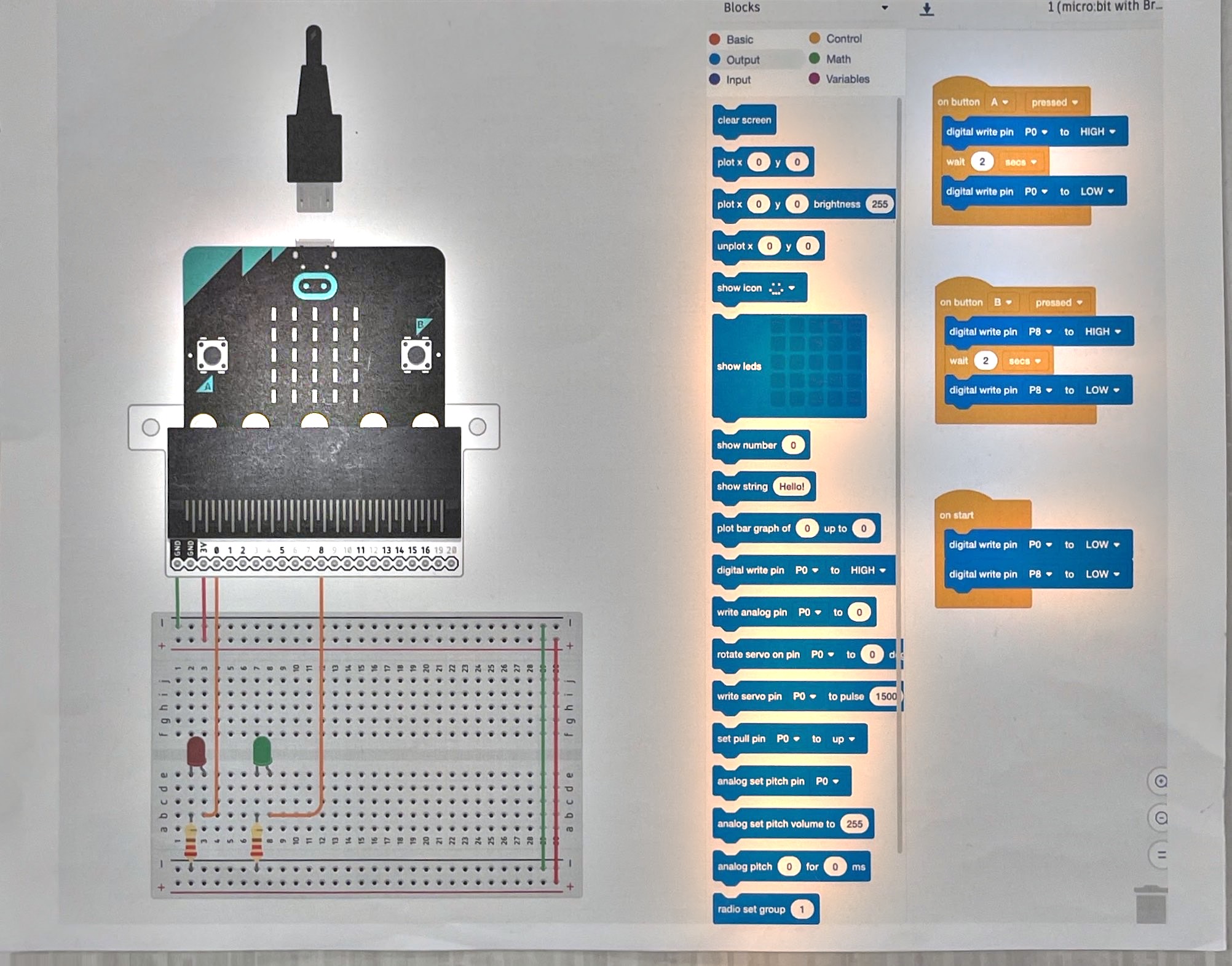
A program is a break in the loop it controls
Lesson 2 was a switch: a person closes the loop. Lesson 4 was a
photoresistor: the room closes the loop. Diagram 8 is the same loop again,
closed by a program instead — button A pressed calls for pin P0 high, waits
2 seconds, then sets it low again; button B does the same on pin P8. The
on start block sets both pins low before anything else runs, so the LEDs
begin off rather than in whatever state the pins happened to power up in.
The loop being closed by code rather than a finger doesn’t change what’s happening electrically. It’s still current flowing because a pin went high, same as every LED circuit before this one — it’s only the decider that changed.
Code can do more than open and shut
A switch or a button is binary: open or closed, on or off. Diagram 9 shows
code doing something neither a switch nor a photoresistor can — a forever
loop continuously reads the micro:bit’s own tilt (pitch and roll) and
writes it as an analog value to an LED, while separately reading the light
sensor and using it to aim a servo, rather than just switching it on.
Code can turn one input into a different, continuously varying output — not
just open and shut a loop, but decide where a loop points.
That’s the honest end of this sequence: a model — Ohm’s law, power, all of it — is trustworthy inside the assumptions it was built on, and silent outside them. Eight circuits in, you’ve earned the right to be told that.
Questions
- Diagram 8’s LEDs are switched fully on or fully off. Diagram 9’s LED is driven by an analog write instead. What can an analog write do that a digital write on diagram 8 can’t?
- If a robot’s motor and its controller board share a power supply, and the motor draws a current spike, what happens to the controller?